This section will show you how to build this clock
:
PIC16F84 microcontroller
4 x 7 segments LED display
Hours and minutes, or minutes and seconds are displayed,
with a control button
DCF77 atomic clock, automatic time set-up
and make it run on a EasyPic development circuit
board.
The complete schematic, and the C language source code
is freely provided !
1. What is DCF77 ?
DCF77 is the name of a german radio station on 77.5 KHz, which gives
official time and date from an atomic clock located in Francfort. The time and
date is coded into a 59 bit length frame, and is sent on the air through an
antenna, by a 50 kilowatt power amplifier.
A simple and tiny receiver can catch the signal, from approximately 2000
kilometers around the antenna. The pulse contained in the radio frequency signal
is filtered by the receiver : a 100 ms pulse is a value of 0, a 200 ms pulse is
a value of 1, there is a pulse per second, and the last second of a minute lacks
(there is 2 seconds without pulse) to allow synchronisation with the next
minute.
There are many good web sites about DCF77, I strongly recommend to visit the
official DCF77 web site :
it contains all that you have to know about DCF-77. You can also try a Google search on DCF77 and select the most appropriate result
for your convenience.
2. How to build a DCF77 receiver ?
You don't need to build yourself a DCF77 receiver :
there are ready-made, cheap modules to buy on internet, ask also your
local dealer.
I tried a few ones, their costs vary from 12 to 18 , all work very
well.
You will have to refer to the datasheet that comes with it, to connect it
properly. They have 3 pins :
Gnd : to be grounded to the 0 V of the power supply
Pulse : output pin
Vcc : power supply, they all work fine with a +5 V power supply, please see
your datasheet for limits.
Some of them are using positive logic (the pulse is a rising edge from 0 volt
to the voltage power supply, followed by a falling edge to 0 volt), others are
using negative logic (the pulse is a falling edge from the voltage power supply
to 0 volt, and a rising edge to the voltage power supply). Don't worry about
this : the software of the clock handles the both of them ! You will just have
to add a pull-up resistor on the pulse output in case of negative logic.
The one used for this project, has been bought to my Electronic
Diffusion local dealer for a cost of 15 (negative logic).
3. My DCF77 board
Once the DCF77 module in hand, you will note how fragile is it !
First, You will have to mount it on a rigid circuit board, otherwise its tiny
circuit board will break from the antenna quickly.
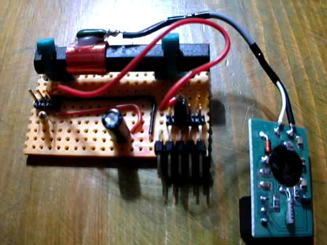
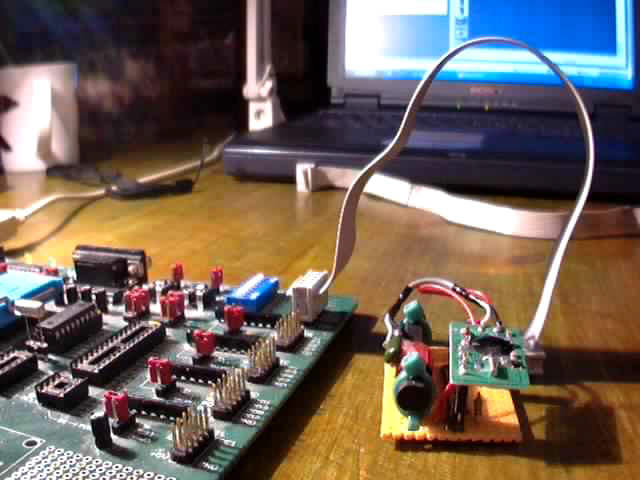
This is how I managed to build my circuit board :
On this picture you can see :
the vertical ferrit antenna, connected to the receiver circuit board (on the
right). The ferrit stick is firmly attached to the veroboard with plastic straps
a 3 pins male connector (on the left), to plug the receiver circuit board on
which a 3 pins female connector has been soldered, from left to right : Ground,
signal output, Vcc.
a vertical pull-up resistor : any value from 4.7 k to 10 k will work
a vertical chemical capacitor for decoupling the power supply : any value
from 10 µF to 220 µF will work
a 4 pins male connector (see below)
a 2 x 5 pins male connector (see below)
and the receiver with its black resin to protect the circuit, with
its little crystal.
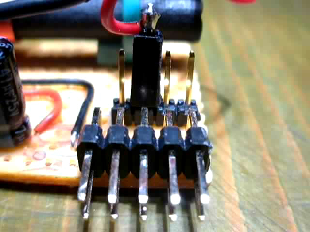
This is a close-up picture of the connectors :
The 2 x 5 male pins will be connected to the EasyPic circuit board : it
matches exactly its layout, so that an simple flat cable will allow to
connect the two circuit boards.
This is the pinout description of the connector :
Pin number, from left to right
1
2
3
4
5
Upper line
+5V
bit #6
bit #4
bit #2
bit #0
Lower line
Gnd
bit #7
bit #5
bit #3
bit #1
Behind, we can see 4 pins : they are facing and connected to the pins 0, 2,
4, 6 of the connector, so that it is possible to choose the even io pin number
of the microcontroller port, on which we want the DCF77 signal pulse to be
connected. Just adjust it with the female socket, it is connected to the output
of the receiver on its other extremity.
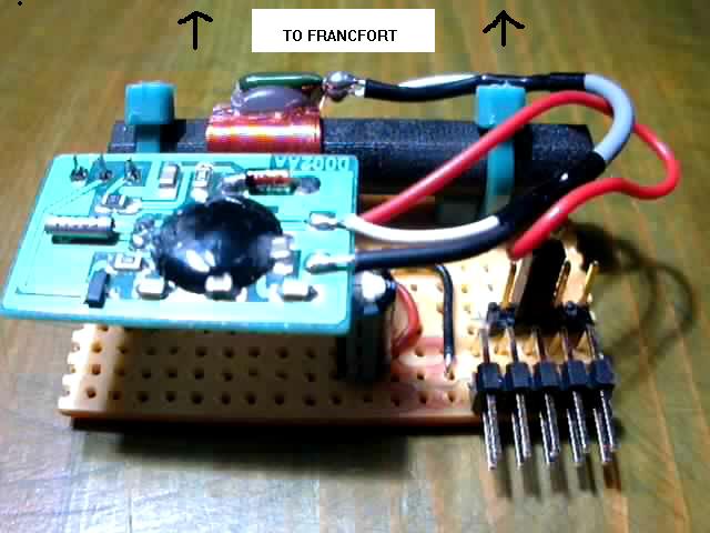
This is my circuit board, ready to be connected to the EasyPic circuit board
:
As you can see, the output pulse of the receiver is wired to bit #4
of the microcontroller port.
The ferrit stick must be perpendicular to Francfort direction, to have the
best radio signal quality.
Here is the receiver circuit board, connected to the EasyPic circuit board
:
As you can see, the receiver is connected to the PORT A of the
microcontroller.
At this time, the DCF77 hardware of the project is ready !
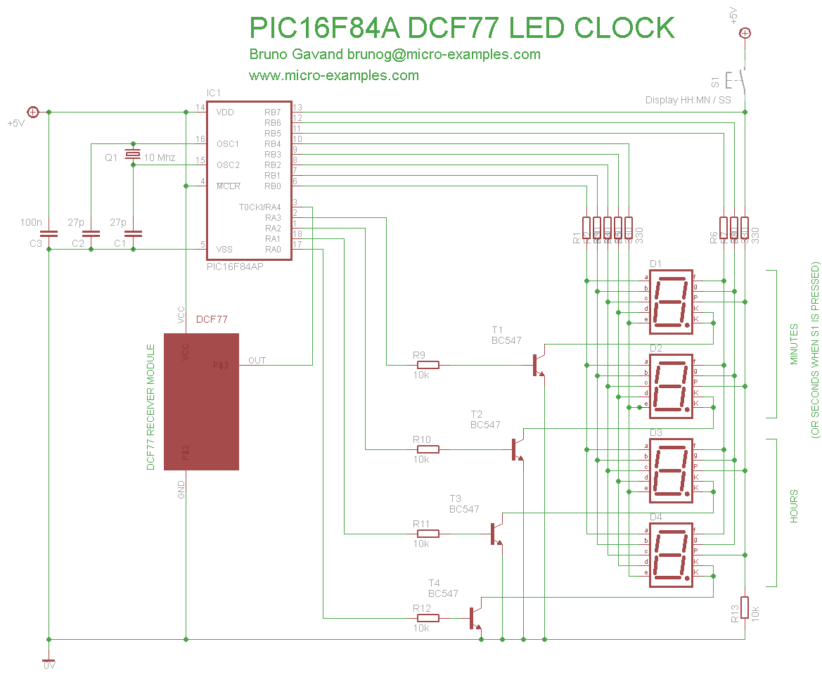
Here is the equivalent circuit schematic (clic
to enlarge) :
4. EasyPic setup
This section will be very short ! Here is what you have to
do :
put a PIC16F84A in the 18-pins socket (ensure that it will work at the speed
we need)
put a 10 Mhz crystal in the socket
set to OFF all switches, except the ones who enable the 7 segments LED
display
remove all pull-up jumpers
remove all extra I/O jumpers : no DS1820, no MAX232, no A/D potentiometer,
etc...
That's all !
5. Write the PIC
It's time to write the program into the PIC !
Here is the .HEX file : download it, read it in the PICFLash programmer
and write it !
First, you will have to adjust the orientation of the ferrit stick,
perpendicularly to the direction of Francfort, in order to have a radio
signal as strong as possible.
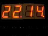
The DCF77 pulse is shown on the decimal point of the second LED display unit
: when the receiver is correctly turned, the LED of the decimal point must
flash regularly. Adjust the orientation if it is not good.
You may also have to turn off all devices that could perturb the radio waves
: TV set, cellular or wireless phones, computer and screen display, and so on,
until you will get a good signal pulse. The 2 digits of the right will then
increment each second : the clock is waiting for a complete DCF77 frame.
Watch the video :
The display has two different modes, which depend on the clock state :
Clock not locked :
In this state, the clock can't display time because it has never received a
complete DCF77 time frame. The clock is in this state at start time.
The first two digits of the digits are blanked, and the two last digits show
the current bit number of the frame in progress.
The decimal point of the second digit shows the pulse signal.
The decimal point of the last digit is a correct frame indicator, it is set
when no error has occured in the current frame.
If a pulse error occurs, or if a parity error is detected, the bit number is
reset, the frame indicator is cleared, and a new count starts.
If a new frame is detected, the frame indicator is set.
When a frame is completed, the bit number 59 is shown for 2 secondes,
and then the clock locks, and time is displayed.
Clock locked :
The pulse signal and the frame indicator act like in unlocked mode, the
clock still continues to receive DCF77 frames
The first two digits show the hours, the next two ones show the minutes
While pressing the RB7 switch, the first two digits show the minutes, and
the next two ones show the secondes. All decimal points are set, because the RB7
pin is used both for driving decimal points of the display, and for reading the
switch.