A simple PIC16F84A alarm clock with programmable weekly alarms.
Overview
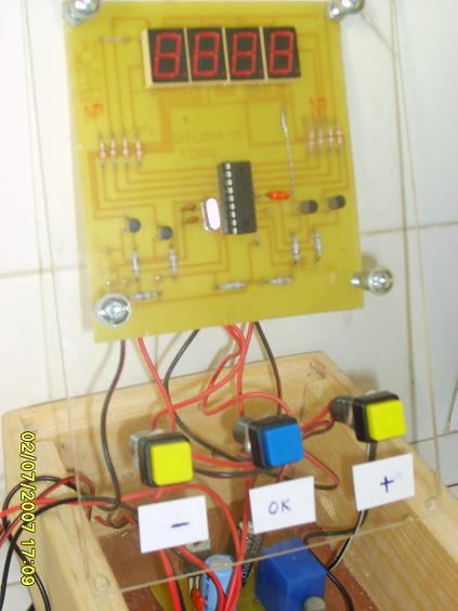
A simple PIC16F84A alarm clock. Counts seconds, minutes, hours and day of the week. Time displayed on 4 seven segment LED displays, adjustable with three buttons (up, down, enter).
Programmable day, hour, minute and duration of alarms. Alarm output on RA4 open collector. Program is in BASIC (mikroBasic). Target: PIC16F84A, 16 MHz crystal.
Circuit Schematic
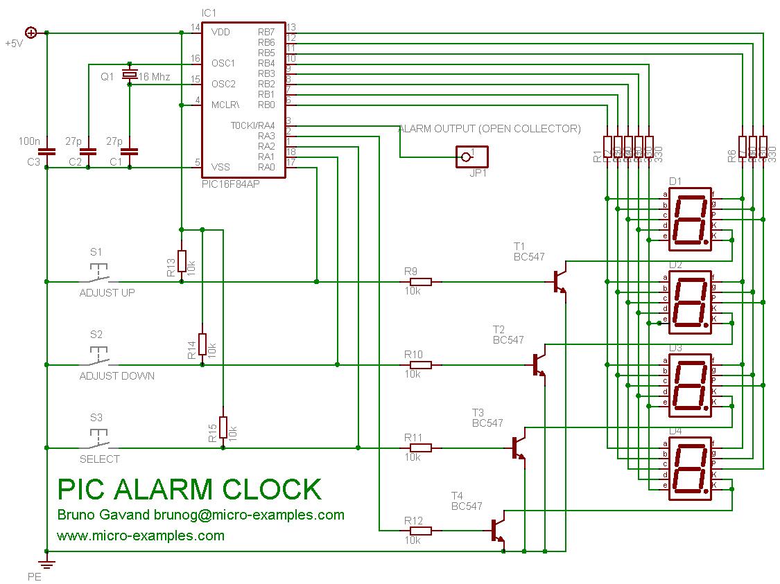
Alarm clock circuit schematic
Basic Source Code
alarmClock.bas
'******************************************************************************
' PIC16F84A ALARM CLOCK
'******************************************************************************
'
' feel free to use this code at your own risks
'
' target : PIC16F84A, 16 Mhz crystal
' HS clock, no watchdog.
'
'******************************************************************************

program alarmClock

'
' if you are using COMMON CATHODE LED display, uncomment this definition.
' if you are using COMMON ANODE LED display, comment this definition.
'
'#define CATHODE_COMMUNE

symbol  LUNDI           = 0     ' monday
symbol  MARDI           = 1     ' thuesday
symbol  MERCREDI        = 2     ' wednesday
symbol  JEUDI           = 3     ' thursday
symbol  VENDREDI        = 4     ' friday
symbol  SAMEDI          = 5     ' saturday
symbol  DIMANCHE        = 6     ' sunday
symbol  LMMJV           = 7     ' from monday to friday included

'
' alarm definitions, to be changed on your needs
'
symbol  NBALARM         = 16    ' number of programmed alarms

const   alarmTable   as byte[NBALARM * 4] = (
'       DAY             HOUR    MINUTE  DURATION (in seconds, max is 59)
        LUNDI,          8,      30,     10,
        LUNDI,          12,     30,     10,
        LUNDI,          14,     00,     10,
        LUNDI,          16,     30,     10,
        MARDI,          8,      30,     10,
        MARDI,          12,     30,     10,
        MARDI,          14,     00,     10,
        MARDI,          16,     30,     10,
        JEUDI,          8,      30,     10,
        JEUDI,          12,     30,     10,
        JEUDI,          14,     00,     10,
        JEUDI,          16,     30,     10,
        VENDREDI,       8,      30,     10,
        VENDREDI,       12,     30,     10,
        VENDREDI,       14,     00,     10,
        VENDREDI,       16,     30,     10
        )

dim maxcount    as word         ' number of TMR0 overflow per second
dim scaler      as word         ' RTC scaler
dim jj          as byte         ' day of week, 0 is monday
dim hh          as byte         ' hour
dim mn          as byte         ' min
dim ss          as byte         ' sec
dim digiled     as byte[4]      ' 4 x 7 segment table
dim digit       as byte         ' current digit to display
dim dp          as byte         ' decimal point
dim key         as byte         ' key code
dim alarm       as byte         ' alarm flag

'
' the ISR works as real time clock
'
sub procedure interrupt
        dim i as byte

        scaler = scaler + 1
        if scaler > maxcount
        then
                scaler = 0
                inc(ss)
                if ss = 60
                then
                        ss = 0
                        inc(mn)
                        if mn = 60
                        then
                                mn = 0
                                inc(hh)
                                if hh = 24
                                then
                                        hh = 0
                                        inc(jj)
                                        if jj = 8
                                        then
                                                jj = 1
                                        end if
                                end if
                        end if
                end if
        end if

' LED display
#ifdef CATHODE_COMMUNE
        PORTA = PORTA and $f0
        TRISA = $0f
        key = PORTA
        TRISA = 0
        PORTB = 0
#else
        PORTA = PORTA or $0f
        TRISA = $0f
        key = PORTA
        key = not(key)
        TRISA = 0
        PORTB = $ff
#endif
        key = key and $07

        digit = digit + 1
        if digit > 3
        then
                digit = 0
                i = $01
        else
                i = $01 << digit
        end if

#ifdef CATHODE_COMMUNE
        PORTB = digiled[digit]
        PORTA = PORTA or i
#else
        PORTB = digiled[digit]
        PORTB = not(PORTB)
        PORTA = PORTA and not(i)
#endif

        INTCON.T0IF = 0
end sub

' converts digit to 7 segment
sub function intTo7seg(dim n as byte) as byte
        select case n
                case 0  result = $3F
                case 1  result = $06
                case 2  result = $5B
                case 3  result = $4F
                case 4  result = $66
                case 5  result = $6D
                case 6  result = $7D
                case 7  result = $07
                case 8  result = $7F
                case 9  result = $6F
        end select
end sub

' select a value with keys
sub procedure setValue(dim v as ^byte, dim s as byte, dim max as byte)
        digiled[0] = s
        digiled[1] = 0

        while 1
                if key.0
                then
                        inc(v^)
                        if(v^ > max)
                        then
                                v^ = 0
                        end if
                end if

                if key.1
                then
                        if(v^ = 0)
                        then
                                v^ = max
                        else
                                dec(v^)
                        end if
                end if

                if key.2
                then
                        Delay_ms(50)
                        while key.2
                        wend
                        Delay_ms(50)
                        scaler = 0
                        ss = 0
                        return
                end if

                digiled[2] = intTo7seg(v^ / 10)
                digiled[3] = intTo7seg(v^ mod 10)

                delay_ms(300)
        wend
end sub

' program entry
main:
        dim i as byte

        dp = 0
        hh = 0
        mn = 0
        ss = 0
        jj = 0
        maxcount = 15625

        PORTA = %00010000
        TRISA = %00000000
        PORTB = 0
        TRISB = $00

        INTCON = %10100000
        OPTION_REG = %11011000

        Delay_ms(50)

' clock adjustment
        setValue(@hh, 116, 23)
        setValue(@mn, 55, 59)
        setValue(@jj, 14, 6)

' forever loop
        while true
                if key
                then
                        digiled[0] = intTo7seg(jj)
                        digiled[1] = 0
                        digiled[2] = intTo7seg(ss / 10)
                        digiled[3] = intTo7seg(ss mod 10)
                else
                        if hh < 10
                        then
                                digiled[0] = 0
                                digiled[1] = intTo7seg(hh)
                        else
                                digiled[0] = intTo7seg(hh / 10)
                                digiled[1] = intTo7seg(hh mod 10)
                        end if
                        digiled[2] = intTo7seg(mn / 10)
                        digiled[3] = intTo7seg(mn mod 10)
                end if

' blinks semicolon
                if scaler > maxcount / 2
                then
                        dp.1 = 1
                else
                        dp.1 = 0
                end if

                digiled[0].7 = dp.0
                digiled[1].7 = dp.1
                digiled[2].7 = dp.2
                digiled[3].7 = dp.3

' check for alarm condition
                alarm = 0
                for i = 0 to (NBALARM - 1) * 4
                        if ((alarmTable[i] = jj) or ((alarmTable[i] = LMMJV) and (jj < SAMEDI)))
                                        and (alarmTable[i + 1] = hh)
                                        and (alarmTable[i + 2] = mn)
                                        and (alarmTable[i + 3] > ss)
                        then
                                inc(alarm)
                        end if
                next i

                if alarm
                then
                        dp.3 = 1
                        PORTA.4 = 0
                else
                        dp.3 = 0
                        PORTA.4 = 1
                end if
        wend
end.
Note
No separate project ZIP file was provided for this project. The source code above is the complete mikroBasic program — copy and paste it into your mikroBasic IDE to build the project.
Notes
- Can be built for common cathode or common anode LED display.
- The number of alarms is limited by ROM space only.
- The alarm table includes 16 programmable entries.