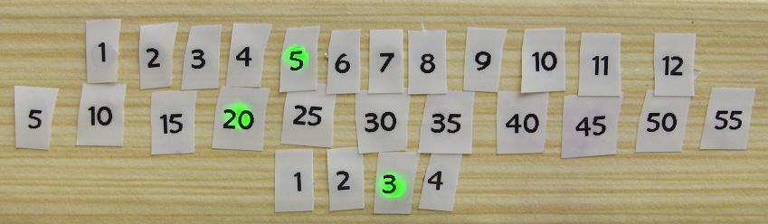
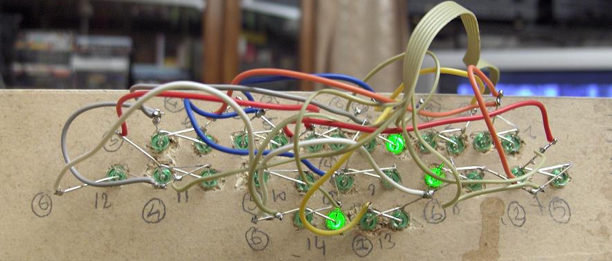
Take a piece of wood, drill 27 holes, insert LEDs, and use a Dymo labeler for the numbers.
Overview
Take a piece of wood, drill 27 5mm holes, insert LEDs, use a Dymo labeler for numbers, wire to a PIC. This project shows how to connect up to 30 LEDs using only six I/O pins.
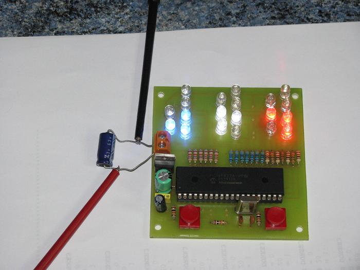
The DymoClock is a 12-hour clock with 27 LEDs and a 2C resolution thermometer, all driven by a single PIC16F819 microcontroller.
Circuit Schematic
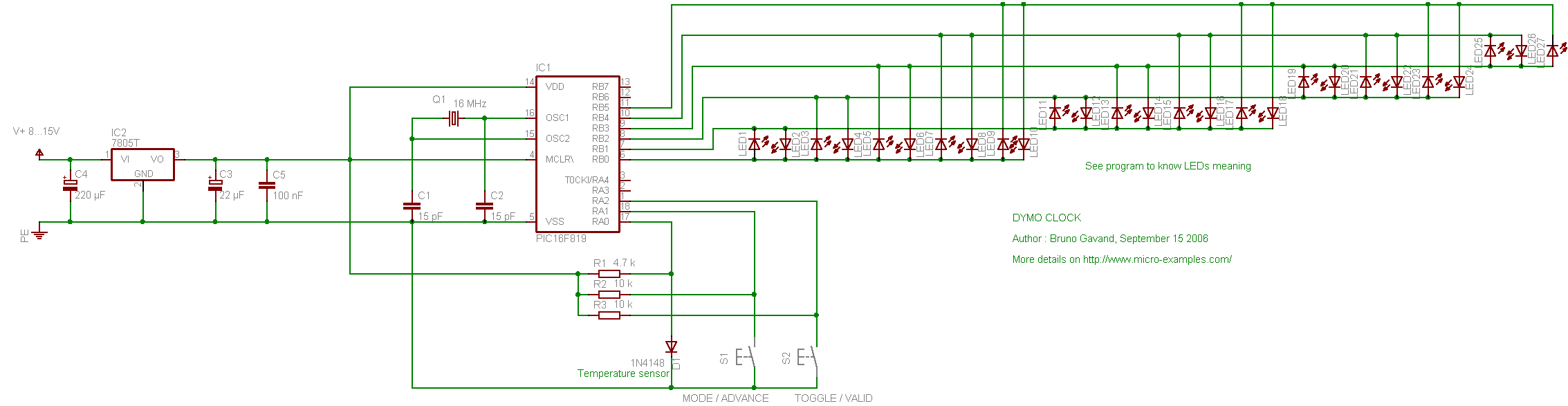
Built around the 18-pin PIC16F819. The LED driving technique comes from Microchip Application Note AN234, using 25 mA LEDs without current limiting resistors. A silicon diode serves as the temperature sensor.
Display Modes
The DymoClock has three display modes:
- Hours:Minutes — displays the current time
- Seconds — displays the seconds count
- Temperature — displays the ambient temperature
The MODE button cycles between the three display modes. The TOGGLE button enables auto-switching between modes. Pressing both buttons simultaneously enters the time setting mode.
C Source Code
/* * file : dymoclock.c * project : Simple LED clock with thermometer * compiler : mikroC V6.0.0.0 * date : september 15, 2006 * * description : * 12 hours clock with 27 LEDs display, 2C resolution thermometer * * target device : * PIC16F819 with 16 Mhz crystal * * configuration bits : * HS clock, no watchdog, RA5 as MCLR, * brown out detect, LVP disabled, CCP1 on RB2 * ******************************************************************************* */ /* * display modes */ #define MODE_HOURMN 0 // hours:minutes #define MODE_SS 1 // seconds #define MODE_TEMP 2 // temperature #define MAX_MODE 3 /* * buttons */ #define BUTTON ((PORTA.F1 == 0) || (PORTA.F2 == 0)) #define BUTTON_MODE (PORTA.F1 == 0) #define BUTTON_TOGGLE (PORTA.F2 == 0) #define BUTTON_SET ((PORTA.F1 == 0) && (PORTA.F2 == 0)) #define TEMP_REF 115 // silicon junction offset: 600 mV #define MAX_TEMP 20 // number of temperature samples /* * LED multiplexing tables */ const unsigned char hhTable[] = { 0, 1, 2, 3, 4, 7, 8, 13, 14, 5, 6, 9, 10 } ; const unsigned char mnTableH[] = { 0, 0, 0, 0, 0, 15, 15, 15, 15, 15, 16, 16, 16, 16, 16, 23, 23, 23, 23, 23, 24, 24, 24, 24, 24, 11, 11, 11, 11, 11, 12, 12, 12, 12, 12, 17, 17, 17, 17, 17, 18, 18, 18, 18, 18, 19, 19, 19, 19, 19, 20, 20, 20, 20, 20, 27, 27, 27, 27, 27 } ; const unsigned char mnTableL[] = { 0, 22, 21, 25, 26, 0, 22, 21, 25, 26, 0, 22, 21, 25, 26, 0, 22, 21, 25, 26, 0, 22, 21, 25, 26, 0, 22, 21, 25, 26, 0, 22, 21, 25, 26, 0, 22, 21, 25, 26, 0, 22, 21, 25, 26, 0, 22, 21, 25, 26, 0, 22, 21, 25, 26, 0, 22, 21, 25, 26 } ; unsigned char mode ; unsigned char toggleMode ; unsigned int scaler = 0 ; unsigned char hh = 1 ; unsigned char mn = 1 ; unsigned char ss = 0 ; int temp ; unsigned char tdeg[MAX_TEMP] ; unsigned char tidx = 0 ; /* * ISR: called Fosc / 4 / 256 times per second */ void interrupt(void) { if(INTCON.TMR0IF) { scaler++ ; if(scaler == 15625) { scaler = 0 ; ss++ ; if(ss == 60) { ss = 0 ; mn++ ; if(mn == 60) { mn = 0 ; hh++ ; if(hh == 13) { hh = 1 ; } } } } INTCON.TMR0IF = 0 ; } } /* * light LED number n during d milliseconds */ void dymoLight(const unsigned char n, unsigned char d) { switch(n) { case 0 : TRISB = 0b11111111 ; PORTB = 0b00000000 ; break ; case 1 : TRISB = 0b11111100 ; PORTB = 0b00000001 ; break ; case 2 : TRISB = 0b11111100 ; PORTB = 0b00000010 ; break ; case 3 : TRISB = 0b11111010 ; PORTB = 0b00000001 ; break ; case 4 : TRISB = 0b11111010 ; PORTB = 0b00000100 ; break ; case 5 : TRISB = 0b11111001 ; PORTB = 0b00000010 ; break ; case 6 : TRISB = 0b11111001 ; PORTB = 0b00000100 ; break ; case 7 : TRISB = 0b11110110 ; PORTB = 0b00000001 ; break ; case 8 : TRISB = 0b11110110 ; PORTB = 0b00001000 ; break ; case 9 : TRISB = 0b11110101 ; PORTB = 0b00000010 ; break ; case 10 : TRISB = 0b11110101 ; PORTB = 0b00001000 ; break ; case 11 : TRISB = 0b11110011 ; PORTB = 0b00000100 ; break ; case 12 : TRISB = 0b11110011 ; PORTB = 0b00001000 ; break ; case 13 : TRISB = 0b11101110 ; PORTB = 0b00000001 ; break ; case 14 : TRISB = 0b11101110 ; PORTB = 0b00010000 ; break ; case 15 : TRISB = 0b11101101 ; PORTB = 0b00000010 ; break ; case 16 : TRISB = 0b11101101 ; PORTB = 0b00010000 ; break ; case 17 : TRISB = 0b11101011 ; PORTB = 0b00000100 ; break ; case 18 : TRISB = 0b11101011 ; PORTB = 0b00010000 ; break ; case 19 : TRISB = 0b11100111 ; PORTB = 0b00001000 ; break ; case 20 : TRISB = 0b11100111 ; PORTB = 0b00010000 ; break ; case 21 : TRISB = 0b11011110 ; PORTB = 0b00000001 ; break ; case 22 : TRISB = 0b11011110 ; PORTB = 0b00100000 ; break ; case 23 : TRISB = 0b11011101 ; PORTB = 0b00000010 ; break ; case 24 : TRISB = 0b11011101 ; PORTB = 0b00100000 ; break ; case 25 : TRISB = 0b11011011 ; PORTB = 0b00000100 ; break ; case 26 : TRISB = 0b11011011 ; PORTB = 0b00100000 ; break ; case 27 : TRISB = 0b11010111 ; PORTB = 0b00001000 ; break ; case 28 : TRISB = 0b11010111 ; PORTB = 0b00100000 ; break ; case 29 : TRISB = 0b11001111 ; PORTB = 0b00010000 ; break ; case 30 : TRISB = 0b11001111 ; PORTB = 0b00100000 ; break ; } VDelay_ms(d) ; } /* * set clock time */ void setTime() { INTCON.GIE = 0 ; hh = 1 ; for(;;) { dymoLight(hhTable[hh], 20) ; if(BUTTON_MODE) { VDelay_ms(15) ; while(BUTTON_MODE) ; VDelay_ms(15) ; hh++ ; if(hh > 12) { hh = 1 ; } } if(BUTTON_TOGGLE) { VDelay_ms(15) ; while(BUTTON_TOGGLE) ; VDelay_ms(15) ; break ; } } mn = 1 ; for(;;) { dymoLight(mnTableH[mn], 10) ; dymoLight(mnTableL[mn], 10) ; if(BUTTON_MODE) { VDelay_ms(15) ; while(BUTTON_MODE) ; VDelay_ms(15) ; mn++ ; if(mn > 59) { mn = 0 ; } } if(BUTTON_TOGGLE) { VDelay_ms(15) ; while(BUTTON_TOGGLE) ; VDelay_ms(15) ; break ; } } ss = 0 ; INTCON.GIE = 1 ; toggleMode = 0 ; mode = MODE_HOURMN ; } /* * main entry */ void main() { unsigned int loopCtr = 0 ; unsigned int toggleCtr = 0 ; ADCON1 = 0b00001110 ; // RA0 analog, others digital TRISA = 0b11111111 ; PORTA = 0 ; TRISB = 0xff ; // display off INTCON.TMR0IF = 0 ; INTCON.TMR0IE = 1 ; OPTION_REG.T0CS = 0 ; OPTION_REG.PS2 = 0 ; OPTION_REG.PS1 = 0 ; OPTION_REG.PS0 = 0 ; OPTION_REG.PSA = 1 ; // no prescaler setTime() ; for(;;) { loopCtr++ ; toggleCtr++ ; if(BUTTON) { unsigned char b = 0 ; VDelay_ms(15) ; while(BUTTON) { if(BUTTON_SET) { dymoLight(hhTable[0], 1) ; dymoLight(mnTableH[0], 1) ; dymoLight(mnTableL[0], 1) ; VDelay_ms(1000) ; setTime() ; break ; } else if(BUTTON_MODE) { b = 1 ; } else if(BUTTON_TOGGLE) { b = 2 ; } VDelay_ms(15) ; } if(b == 1) { VDelay_ms(15) ; while(BUTTON_MODE) ; VDelay_ms(15) ; mode++ ; toggleMode = 0 ; if(mode == MAX_MODE) { mode = 0 ; } } else if(b == 2) { VDelay_ms(15) ; while(BUTTON_TOGGLE) ; VDelay_ms(15) ; toggleMode = !toggleMode ; } } if(mode == MODE_HOURMN) { dymoLight(hhTable[hh], 5) ; dymoLight(mnTableH[mn], 5) ; dymoLight(mnTableL[mn], 5) ; if(toggleMode && (toggleCtr > 400)) { toggleCtr = 0 ; mode = MODE_TEMP ; } } else if(mode == MODE_SS) { dymoLight(mnTableH[ss], 5) ; dymoLight(mnTableL[ss], 5) ; } else if(mode == MODE_TEMP) { unsigned char i ; if(loopCtr > 20) { loopCtr = 0 ; temp = TEMP_REF - Adc_Read(0) ; temp *= 221 ; temp /= 102 ; temp = 25 + temp ; tdeg[tidx] = temp ; tidx++ ; if(tidx == MAX_TEMP) { tidx = 0 ; } temp = 0 ; for(i = 0 ; i < MAX_TEMP ; i++) { temp += tdeg[i] ; } temp /= MAX_TEMP ; } if((temp > 0) && (temp < 60)) { dymoLight(mnTableL[temp], 5) ; dymoLight(mnTableH[temp], 5) ; } if(toggleMode && (toggleCtr > 200)) { toggleCtr = 0 ; mode = MODE_HOURMN ; } } } }
Note
No separate project ZIP file was provided for this project. The source code above is the complete mikroC program — copy and paste it into your mikroC IDE to build the project.
User Builds
The DymoClock project inspired several community builds and variations:
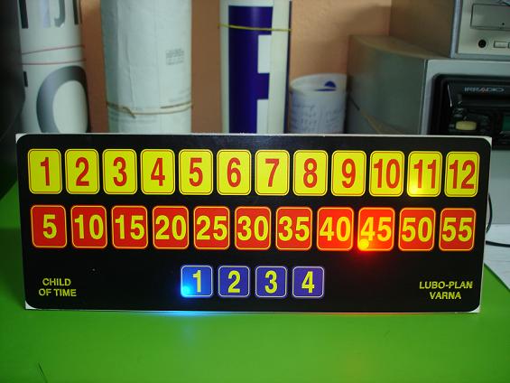
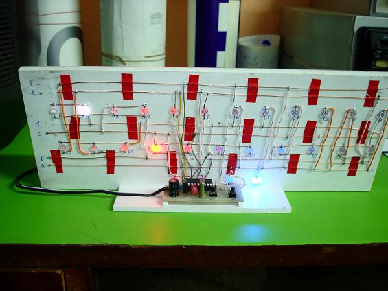
Lubo_plan's DymoClock
A faithful reproduction of the original design:
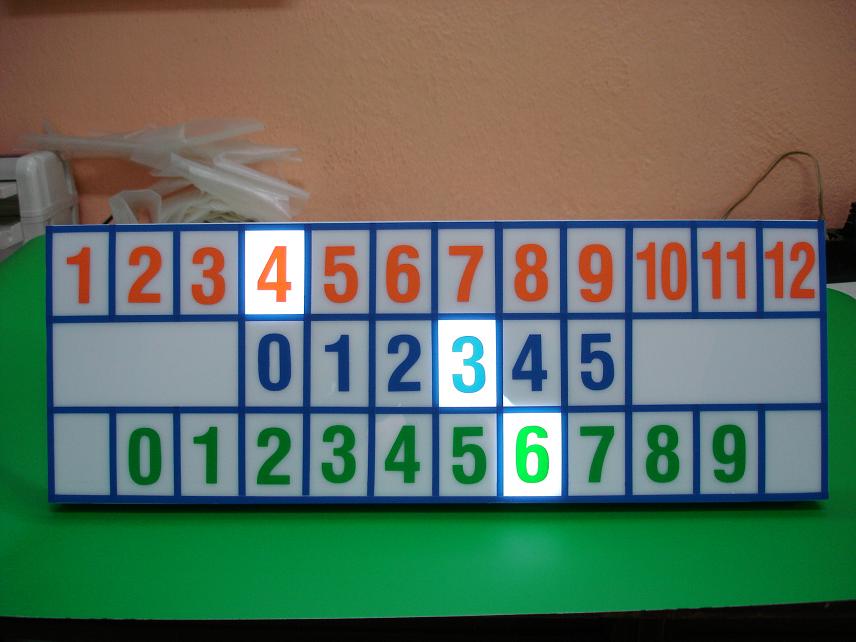
Gerard's Binary Clock
A creative twist using a blue-white-red binary display format: