How to connect your development board to the Ethernet Network using the ENC28J60 Microchip Ethernet Controller.
Overview
How to connect your development board to the Ethernet Network using the ENC28J60 Microchip Ethernet Controller. Turn your EasyPic2 into an Ethernet Toolkit.
Parts List
Components Required
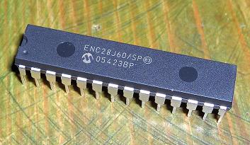
- ENC28J60 Ethernet controller IC
- LP2950CZ-3.3 voltage regulator
- 25 MHz crystal
- LEDs (link and activity indicators)
- Capacitors (decoupling and bulk)
- Resistors: 50 Ohm 1% x4, 2.7K 1%
- FB2022 TX/RX magnetic filter
- RJ45 socket
Circuit Schematic
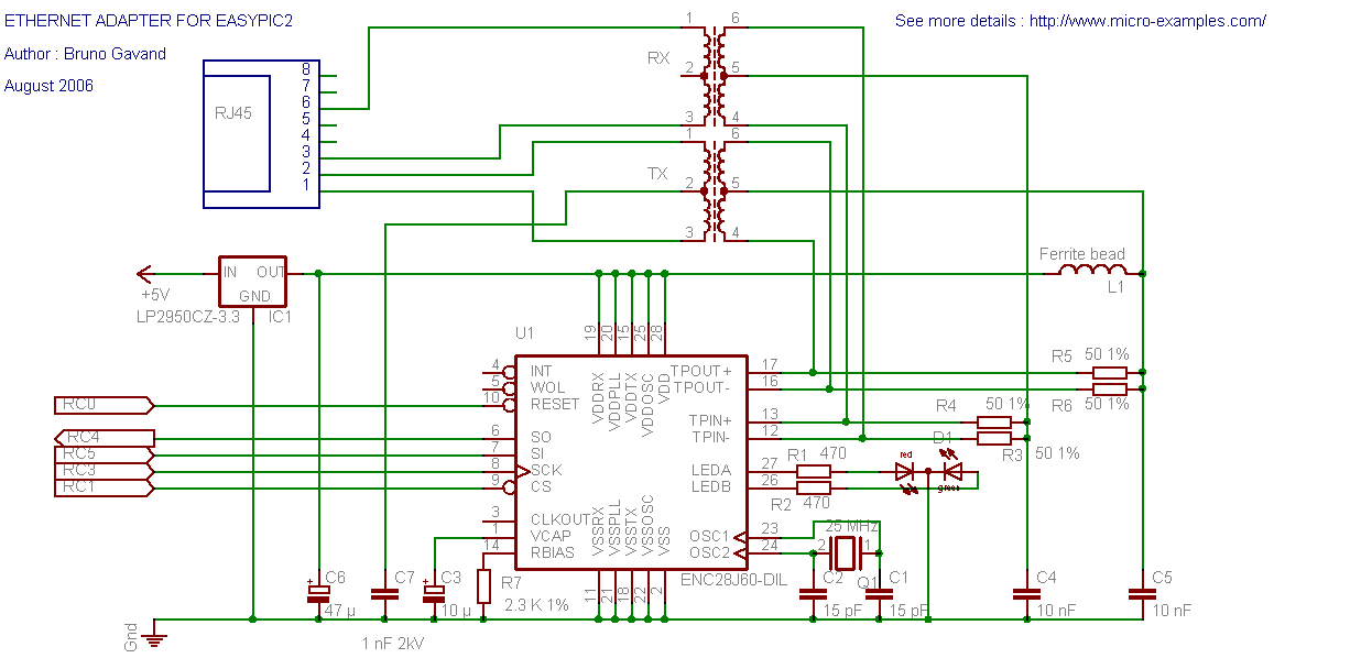
The circuit is based on the ENC28J60 datasheet reference design. The ENC28J60 connects to the network through the magnetic adapter (FB2022) and to the PIC via 5 SPI lines.
The ENC28J60 operates at 3.3V (supplied by the LP2950CZ-3.3 regulator), but its 3.3V outputs are compatible with PIC TTL inputs, so no level shifting is needed.
Assembly
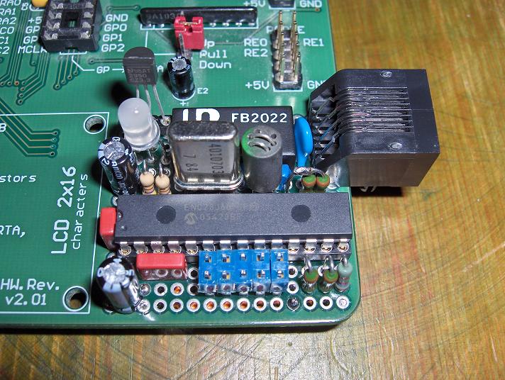
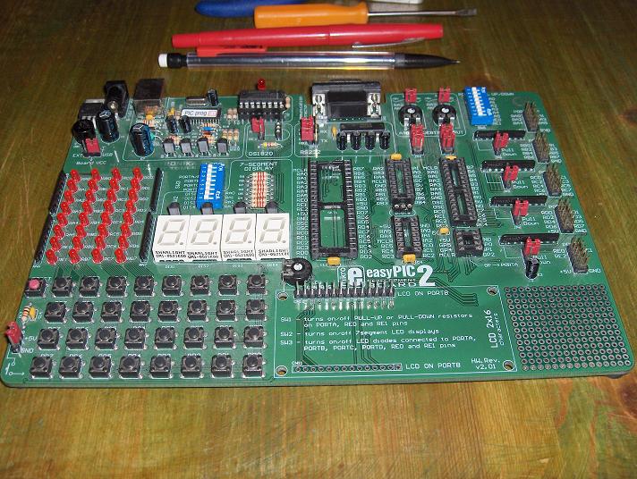
The adapter is built on a small piece of perfboard and connects to the EasyPic2 through the prototyping area. A red/green bicolor LED provides link and activity status. A jumper allows isolating the Ethernet adapter when not in use.
Testing
The test source code verifies SPI communication between the PIC and the ENC28J60:
- Sets LEDA as link status indicator
- Makes LEDB blink to confirm SPI communication
Test results:
- LEDA off + LEDB blinks = SPI communication working, no network link
- Connect to a hub or switch: LEDA on = network link established
// Test SPI communication with ENC28J60
// LEDA = link status, LEDB = SPI activity

// If LEDA off and LEDB blinks: SPI works, no network
// If LEDA on and LEDB blinks: SPI works, network linked