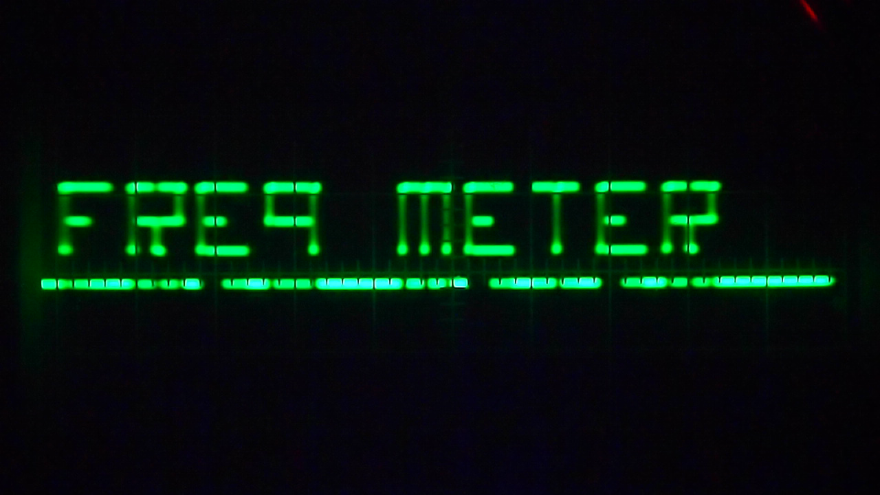
How to display text on an oscilloscope? This project displays alphanumeric characters (0-9, A-Z) on an oscilloscope screen using a simple 8-pin PIC12F683 microcontroller. It functions as both a frequency meter (1 Hz to 1.5 MHz) and a voltmeter (0-5V), with a push button to toggle between modes.
Overview
This project builds on the same idea as PicOClock, but goes much further: instead of just displaying 7-segment digits, PicOscilloMeter uses a 12-segment display format to render full alphanumeric characters (0-9, a-z) on the oscilloscope screen.
A 2-bit R2R ladder DAC made with just 4 resistors generates 4 voltage levels for the oscilloscope Y input. The oscilloscope X trigger is driven by the PIC to synchronize horizontal sweeps.
Key Features
- Frequency meter: 1 Hz to 1.5 MHz range
- Voltmeter: 0-5V range
- Push-button mode toggle
- Up to 15 displayable digits
- Alphanumeric display (0-9, A-Z)
- Only 4 resistors needed for the DAC
- 8-pin PIC12F683, internal 8 MHz clock
Oscilloscope Configuration
- Timebase: 0.5 ms/division
- Vertical scale: 2V/division
- Trigger: External trigger mode (not X/Y mode)
Don't expect a high-precision frequency meter, since the PIC is clocked from the internal oscillator!
Display Encoding
The software implements a 12-segment display format for character representation. Segments are labeled A-L, arranged in three vertical sections per digit. Each digit is rendered across 3 time slots (frames), using retinal persistence to form the complete character on screen.
The frequency meter captures Timer 1 ticks over one-second intervals and automatically ranges between Hz and kHz display above 1 MHz. The voltage meter reads the 10-bit ADC, converts to 0-5V range, and displays in mV below 1V or in volts above 1V.
Circuit Schematic
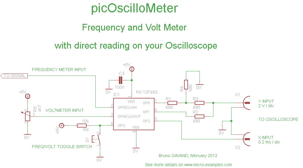
- GP0, GP1: DAC output via 2-bit R2R ladder (two 680 ohm resistors) connected to oscilloscope Y input
- GP2: External trigger output connected to oscilloscope trigger input
- GP3: Push button input (mode toggle: frequency / voltage)
- GP4 (T1CKI): Frequency input for Timer 1 counting
- GP5 (AN3): Analog input for voltage measurement
C Source Code
Target: PIC12F683 with internal 8 MHz oscillator, watchdog disabled. Compiled with mikroC PRO v5.30.
/* ******************************************************************************* * PICOSCILLOMETER : PIC Oscilloscope Meter ******************************************************************************* * * This program shows how to do a direct reading on an oscillocope * to build a frequency meter and a voltmeter * with a PIC and only 4 resistors. * * Circuit schematic : * * ------------+ * GP2 +----------------> to oscilloscope X trigger input * | * PIC | ____ * GP1 +----|____|-----+----------> to oscilloscope Y input * | 680 | * | +-+ * | | | 680 * | +-+ * | ____ | * GP0 +----|____|-----+ * | 680 | * ------------+ +-+ * | | 680 * +-+ * | * ----- * --- GND * - * * Oscilloscope setup : * set timebase to 0.5 ms, V/div = 2 V * select external trigger. * * source code for mikro C PRO compiler V5.30 * feel free to use this code at your own risks * * target : PIC12F683 * internal 8 MHz clock, no watchdog. * ******************************************************************************* */ #include "built_in.h" /* * 2 bits R2R DAC gives 4 output levels : */ #define HIGH GPIO = 0b11 // uper line #define MID GPIO = 0b10 // middle line #define LOW GPIO = 0b01 // lower line #define ZERO GPIO = 0b00 // lowest line #define MAX_DIGIT 15 // number of digits to be displayed #define SLOTS (MAX_DIGIT * 3) // number of time slots, 3 per digit /* * to display text, we need to invent 12 segment digits * SEGMENT NAME : A H ----- ----- | | | F| |B |I | G | L | ----- ----- | | | E| |C |J | | | ----- ----- D K SEGMENT ENCODING : */ #define sA 0x001 #define sB 0x002 #define sC 0x004 #define sD 0x008 #define sE 0x010 #define sF 0x020 #define sG 0x040 #define sH 0x080 #define sI 0x100 #define sJ 0x200 #define sK 0x400 #define sL 0x800 /* * DIGIT ENCODING : */ const unsigned int twelveSeg[] = { sH + sI + sJ + sK + sC + sB, // 0 sI + sJ, // 1 sH + sI + sL + sC + sK, // 2 sH + sI + sL + sJ + sK, // 3 sB + sL + sI + sJ, // 4 sH + sB + sL + sJ + sK, // 5 sH + sB + sC + sK + sJ + sL, // 6 sH + sI + sJ, // 7 sH + sI + sJ + sK + sC + sB + sL, // 8 sL + sB + sH + sI + sJ + sK, // 9 0, // blank 10 sE + sF + sA + sH + sI + sJ + sG + sL, // a 11 sF + sA + sB + sG + sL + sJ + sK + sD + sE, // b sH + sA + sF + sE + sD + sK, // c sI + sL + sG + sE + sD + sK + sJ, // d sH + sA + sF + sG + sE + sD + sK, // e sA + sH + sF + sG + sE, // f sA + sF + sE + sD + sK + sJ + sL, // g sF + sE + sG + sL + sI + sJ, // h sB + sC, // i sI + sJ + sK + sD, // j sE + sF + sG + sL + sI + sC, // k sF + sE + sD + sK, // l sE + sF + sA + sB + sC + sH + sI + sJ, // m sC + sB + sH + sI + sJ, // n sA + sH + sI + sJ + sK + sD + sE + sF, // o sE + sF + sA + sH + sI + sL + sG, // p sJ + sI + sH + sA + sF + sG + sL, // q sE + sF + sA + sH + sI + sL + sG + sC, // r sA + sF + sG + sL + sJ + sK + sD + sH, // s sA + sH + sB + sC, // t sB + sC + sK + sJ + sI, // u sF + sE + sD + sC + sB + sH, // v sF + sE + sD + sC + sB + sK + sJ + sI, // w sA + sH + + sB + sC + sD + sK, // x sF + sG + sL + sI + sJ + sK + sD, // y sA + sB + sC + sK, // z } ; unsigned char display[MAX_DIGIT] ; // text to be displayed /* * time slot flags : * bit 0 is upper horizontal line (segments A or H) * bit 1 is middle horizontal line (segments G or L) * bit 2 is lower horizontal line (segments D or K) * (if no line flag is set, spot is redirected to lowest line) * bit 6 is lower vertical bar (segments E, C or J) * bit 7 is upper vertical bar (segments F, B or I) */ unsigned char line[SLOTS] ; unsigned char dIdx = 0 ; // time slot counter unsigned char fIdx = 0 ; // frame counter #define TICKS_PER_SEC ((Clock_KHz() * 1000) / 4 / 256) unsigned int scaler ; // ticks per second counter unsigned char t1roll ; // timer 1 rollover counter unsigned long t1ctr = 0 ; // timer 1 ticks per second counter unsigned char freqVolt = 0 ; // frequency or volt meter function // welcome message const char welcomeMsg[] = " welcome " ; const char freqMsg[] = " freq meter " ; const char voltMsg[] = " volt meter " ; /* * ISR */ void interrupt(void) { if(INTCON.T0IF) // if timer 0 overflow { if(line[dIdx].F6 && line[dIdx].F7) // if full vertical bar { LOW, HIGH, LOW, HIGH ; LOW, HIGH, LOW, HIGH ; LOW, HIGH, LOW, HIGH ; LOW, HIGH, LOW, HIGH ; LOW, HIGH, LOW, HIGH ; LOW, HIGH, LOW, HIGH ; LOW, HIGH, LOW, HIGH ; LOW, HIGH, LOW, HIGH ; } else if(line[dIdx].F6) // if lower vertical bar { MID, LOW, MID, LOW ; MID, LOW, MID, LOW ; MID, LOW, MID, LOW ; MID, LOW, MID, LOW ; MID, LOW, MID, LOW ; MID, LOW, MID, LOW ; MID, LOW, MID, LOW ; MID, LOW, MID, LOW ; } else if(line[dIdx].F7) // if upper vertical bar { MID, HIGH, MID, HIGH ; MID, HIGH, MID, HIGH ; MID, HIGH, MID, HIGH ; MID, HIGH, MID, HIGH ; MID, HIGH, MID, HIGH ; MID, HIGH, MID, HIGH ; MID, HIGH, MID, HIGH ; MID, HIGH, MID, HIGH ; } switch(fIdx) // depending on frame index { case 0: // upper horizontal line if(line[dIdx] & 1) { HIGH ; } else { ZERO ; } break ; case 1: // middle horizontal line if(line[dIdx] & 2) { MID ; } else { ZERO ; } break ; case 2: // lower horizontal line if(line[dIdx] & 4) { LOW ; } else { ZERO ; } break ; } dIdx++ ; // next slot if(dIdx == SLOTS) // last slot ? { GPIO.F2 = 1 ; // new frame, triggers X scope dIdx = 0 ; fIdx++ ; if(fIdx == 3) { fIdx = 0 ; } } scaler++ ; if(scaler == TICKS_PER_SEC) // check for one second { T1CON.TMR1ON = 0 ; // stop timer Lo(t1ctr) = TMR1L ; // read timer Hi(t1ctr) = TMR1H ; Higher(t1ctr) = t1roll ; // read rollovers TMR1L = 0 ; TMR1H = 0 ; t1roll = 0 ; T1CON.TMR1ON = 1 ; // start timer scaler = 0 ; } INTCON.T0IF = 0 ; } if(PIR1.TMR1IF) // if timer 1 overflow { t1roll++ ; PIR1.TMR1IF = 0 ; } GPIO.F2 = 0 ; // end trigger } /* * returns 12 segment encoding for character cc */ unsigned char mkdigit(const char cc) { unsigned char c ; c = tolower(cc) ; if((c >= '0') && (c <= '9')) { return(c - '0') ; } if((c >= 'a') && (c <= 'z')) { return(c - 'a' + 11) ; } return(10) ; // space if not printable } /* * build time slots from display string */ mkTimeSlots() { unsigned int i ; unsigned char *p ; p = line ; for(i = 0 ; i < MAX_DIGIT ; i++) { unsigned int s ; unsigned char sl, sh ; s = twelveSeg[display[i]] ; sl = Lo(s) ; sh = Hi(s) ; (*p).F7 = sl.F5 ; // f segment (*p).F6 = sl.F4 ; // e segment (*p).F0 = sl.F0 ; // a segment (*p).F1 = sl.F6 ; // g segment (*p).F2 = sl.F3 ; // d segment p++ ; (*p).F6 = sl.F2 ; // b segment (*p).F7 = sl.F1 ; // c segment (*p).F0 = sl.F7 ; // h segment (*p).F1 = sh.F3 ; // l segment (*p).F2 = sh.F2 ; // k segment p++ ; *p = 0 ; (*p).F6 = sh.F1 ; // i segment (*p).F7 = sh.F0 ; // j segment p++ ; } } /* * message scrolling */ void displayMsg(const unsigned char *msg) { unsigned char i ; i = 0 ; while(*msg) { display[i++] = mkdigit(*msg++) ; } mkTimeSlots() ; Delay_ms(1000) ; } /* * main entry */ void main() { unsigned char i ; unsigned long val ; OSCCON |= 0b01110000 ; // select 8 Mhz internal oscillator OSCTUNE = 0 ; // default oscillator calibration CMCON0 = 7 ; // no comparator TRISIO = 0b111000 ; // pin direction ANSEL = 0b010000 ; // configure GPIO 4 for DAC /* * clear buffers */ for(i = 0 ; i < sizeof(line) ; i++) { line[i] = 0 ; } for(i = 0 ; i < sizeof(display) ; i++) { display[i] = 0 ; } T1CON = 0b00000011 ; // external clock OPTION_REG = 0b11011000 ; PIE1.TMR1IE = 1 ; // enable timer 1 rollover interrupt PIR1.TMR1IF = 0 ; INTCON = 0b11100000 ; // start interrupts displayMsg(welcomeMsg) ; for(;;) // main loop { /* * toggle frequency/volt meter */ if(GPIO.F3 == 0) { freqVolt ^= 1 ; if(freqVolt) { displayMsg(freqMsg) ; } else { displayMsg(voltMsg) ; } while(GPIO.F3 == 0) ; Delay_ms(200) ; } memset(display, 10, MAX_DIGIT) ; // clear display if(freqVolt) { // frequency meter val = t1ctr ; if(t1ctr >= 1000000L) // auto range { val /= 1000L ; display[10] = mkdigit('k') ; display[11] = mkdigit('h') ; display[12] = mkdigit('z') ; } else { display[10] = mkdigit('h') ; display[11] = mkdigit('z') ; } display[2] = (val / 100000) % 10 ; display[3] = (val / 10000) % 10 ; display[4] = (val / 1000) % 10 ; display[5] = 10 ; // separator display[6] = (val / 100) % 10 ; display[7] = (val / 10) % 10 ; display[8] = (val / 1) % 10 ; /* clear leading 0s */ if(display[2] == 0) { display[2] = 10 ; if(display[3] == 0) { display[3] = 10 ; if(display[4] == 0) { display[4] = 10 ; if(display[6] == 0) { display[6] = 10 ; if(display[7] == 0) { display[7] = 10 ; } } } } } } else { /* volt meter */ val = Adc_Read(3) ; // read ADC channel 3 val *= 5000 ; val /= 1024 ; if(val < 1000) // auto range { /* display mV */ display[6] = (val / 100) % 10 ; display[7] = (val / 10) % 10 ; display[8] = (val / 1) % 10 ; if(display[6] == 0) { display[6] = 10 ; if(display[7] == 0) { display[7] = 10 ; } } display[9] = mkdigit(' ') ; display[10] = mkdigit('m') ; display[11] = mkdigit('v') ; } else { /* display V */ display[4] = (val / 1000) % 10 ; display[5] = mkdigit('v') ; display[6] = (val / 100) % 10 ; display[7] = (val / 10) % 10 ; display[8] = (val / 1) % 10 ; } } mkTimeSlots() ; // prepare time slot Delay_ms(100) ; // short delay for display } }
Download project
PicOscilloMeter project files
Download PicOscilloMeter_project.ZIP file for mikroC PRO:
Includes:
- mikroC PRO project files for PIC12F683
- Complete C source code
- Pre-compiled .HEX files ready for programming