Views
Views
(→PicoOClock : Turn your oscilloscope into a digital clock) |
(→PicoOClock : Turn your oscilloscope into a digital clock) |
||
| (13 intermediate revisions by one user not shown) | |||
| Line 1: | Line 1: | ||
| − | + | Your are proud of your expensive oscilloscope, now you can turn it into a cheap digital clock ! | |
| + | |||
| + | How to display a clock on an oscilloscope | ||
==PicoOClock : Turn your oscilloscope into a digital clock== | ==PicoOClock : Turn your oscilloscope into a digital clock== | ||
| − | + | A short video clip is sometimes better than a long explanation : | |
{{#ev:youtube|MJ79od3IYmM}} | {{#ev:youtube|MJ79od3IYmM}} | ||
| − | + | ''See also : [[PicOscilloMeter]] project !'' | |
| − | By using X/Y mode, where the spot is controlled on two axes by two different voltages, it is possible to draw a picture (as in the examples mentioned | + | For those are not into electronics, you must know that an [[wikipedia:oscilloscope|oscilloscope]] has basicaly only one timebase to move the spot horizontaly from left to right with the same intensity. The vertical deviation is function to the input voltage. You understand immediately that you can't directly display 7 segment digits, because you can't move the spot from right to left. |
| + | |||
| + | By using X/Y mode, where the spot is controlled on two axes by two different voltages, it is possible to draw a picture (as in the examples mentioned below), but a fast digital to analog converter with two channels and at least 8 bits of resolution would be needed. | ||
So we have to deal with a spot that always goes from left to right in the same period of time. | So we have to deal with a spot that always goes from left to right in the same period of time. | ||
| Line 14: | Line 18: | ||
vertical segments : easy to do, just change voltage up and down quickly a few times. | vertical segments : easy to do, just change voltage up and down quickly a few times. | ||
horizontal segments : easy to do, just set a voltage level and keep it as long as you need. | horizontal segments : easy to do, just set a voltage level and keep it as long as you need. | ||
| − | By using 2 PIC outputs and a basic R2R digital to analog converter, we can have up to four different voltage levels : 3 for the vertical segment, and another one where to put the spot when it is not in use to draw a segment. | + | By using 2 PIC outputs and a basic [[wikipedia:Resistor ladder|R2R digital to analog converter]], we can have up to four different voltage levels : 3 for the vertical segment, and another one where to put the spot when it is not in use to draw a segment. |
But the problem is that a 7 segment digit may have up to 3 horizontal lines at a time (like 2, 3, 8, 9..) but we can draw only one during one spot deviation. | But the problem is that a 7 segment digit may have up to 3 horizontal lines at a time (like 2, 3, 8, 9..) but we can draw only one during one spot deviation. | ||
So we will have to cheat with retinal persistance and use multiple frames : since we can have only one vertical segment per period, three periods will be needed to draw a full 7 segment digit. | So we will have to cheat with retinal persistance and use multiple frames : since we can have only one vertical segment per period, three periods will be needed to draw a full 7 segment digit. | ||
| − | |||
{| border=1 | {| border=1 | ||
| Line 47: | Line 50: | ||
|} | |} | ||
| − | + | How to use PicOClock : | |
* Connect X1 (see circuit schematic) to the Y input (vertical deviation) of the oscilloscope | * Connect X1 (see circuit schematic) to the Y input (vertical deviation) of the oscilloscope | ||
* Connect X2 (see circuit schematic) to the external trigger input of the oscilloscope | * Connect X2 (see circuit schematic) to the external trigger input of the oscilloscope | ||
| Line 62: | Line 65: | ||
==Circuit Schematic== | ==Circuit Schematic== | ||
[[File:PicoClock-schematic.jpg]] | [[File:PicoClock-schematic.jpg]] | ||
| − | * a 2-bit digital to analog converter is made by resistor ladder R3...R6 driven by RB0 and RB1 output ports | + | * a 2-bit digital to analog converter is made by [[wikipedia:Resistor ladder|resistor ladder]] R3...R6 driven by RB0 and RB1 output ports |
* RA0 triggers oscilloscope vertical sync | * RA0 triggers oscilloscope vertical sync | ||
| Line 397: | Line 400: | ||
==Download project== | ==Download project== | ||
| − | + | Please copy/paste C source code above in your favorite PIC C compiler ! | |
| + | [[Category:Projects]] | ||
| + | [[Category:PIC16]] | ||
| − | + | ==External links to other projects of the same kind== | |
| − | + | * http://www.franktechniek.nl/Kits/oscilloscopeclock/oscilloscopeclock.htm : analog/digital clock using X/Y mode | |
| − | + | * http://dutchtronix.com/ScopeClock.htm : analog/digital clock using X/Y mode | |
| − | * | + | * http://www.retrothing.com/2006/06/the_oscilliscop.html : CRT clock, very nice work |
| − | * | + | |
| − | + | ||
| − | + | ||
==Discussion and comments== | ==Discussion and comments== | ||
| + | {{#w4grb_rate:}} | ||
<discussion /> | <discussion /> | ||
Latest revision as of 23:49, 16 February 2012
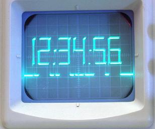
Your are proud of your expensive oscilloscope, now you can turn it into a cheap digital clock !
How to display a clock on an oscilloscope
Contents |
PicoOClock : Turn your oscilloscope into a digital clock
A short video clip is sometimes better than a long explanation :
See also : PicOscilloMeter project !
For those are not into electronics, you must know that an oscilloscope has basicaly only one timebase to move the spot horizontaly from left to right with the same intensity. The vertical deviation is function to the input voltage. You understand immediately that you can't directly display 7 segment digits, because you can't move the spot from right to left.
By using X/Y mode, where the spot is controlled on two axes by two different voltages, it is possible to draw a picture (as in the examples mentioned below), but a fast digital to analog converter with two channels and at least 8 bits of resolution would be needed.
So we have to deal with a spot that always goes from left to right in the same period of time. If we want to have a 7segment-like display, we have to draw :
vertical segments : easy to do, just change voltage up and down quickly a few times. horizontal segments : easy to do, just set a voltage level and keep it as long as you need. By using 2 PIC outputs and a basic R2R digital to analog converter, we can have up to four different voltage levels : 3 for the vertical segment, and another one where to put the spot when it is not in use to draw a segment.
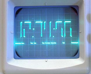
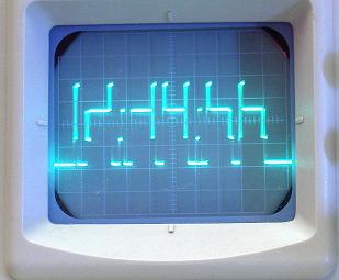
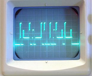
But the problem is that a 7 segment digit may have up to 3 horizontal lines at a time (like 2, 3, 8, 9..) but we can draw only one during one spot deviation. So we will have to cheat with retinal persistance and use multiple frames : since we can have only one vertical segment per period, three periods will be needed to draw a full 7 segment digit.
How to use PicOClock :
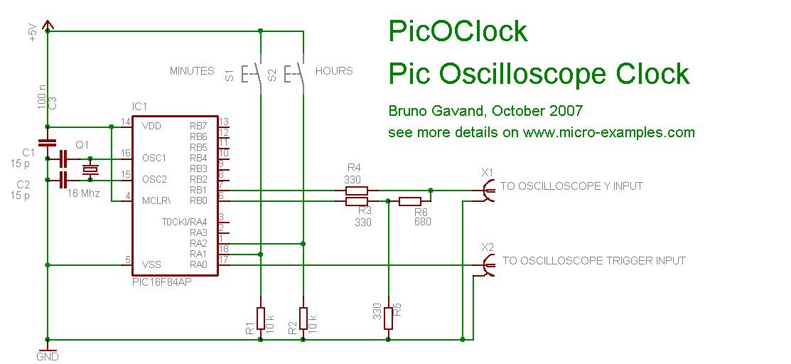
- Connect X1 (see circuit schematic) to the Y input (vertical deviation) of the oscilloscope
- Connect X2 (see circuit schematic) to the external trigger input of the oscilloscope
- Set on your oscilloscope :
- timebase to 0.1 ms
- vertical deviation 1/V division
- external trigger
- Power the circuit : display starts with 0:00:00
- Press hours button to change hours
- Press minutes button to change minutes
If you like it, please see also my Pic Pal Video Library, and also PicoOSD
Circuit Schematic
- a 2-bit digital to analog converter is made by resistor ladder R3...R6 driven by RB0 and RB1 output ports
- RA0 triggers oscilloscope vertical sync
C Source code
/*
*******************************************************************************
* PICOCLOCK : PIC Oscilloscope CLOCK
*******************************************************************************
*
* This program shows how to display a digital clock on an oscilloscope
* with a PIC and only 4 resistors.
*
* Circuit schematics :
*
* ------------+
* RA0 +----------------> to oscilloscope X trigger input
* |
* RA1 +----------------> pull-up, button to ground : minutes adjustment
* RA2 +----------------> pull-up, button to ground : hours adjustment
* PIC | ____
* RB1 +----|____|-----+---------> to oscilloscope Y input
* | 680 |
* | +-+
* | | | 330
* | +-+
* | ____ |
* RB0 +----|____|-----+
* | 680 |
* ------------+ +-+
* | | 680
* +-+
* |
* -----
* --- GND
* -
*
* Oscilloscope setup :
* set timebase to 0.1 ms, V/div = 1 V
* select external trigger.
*
* source code for mikro C compiler V7.0.0.3
* feel free to use this code at your own risks
* and don't bother me if you get addicted watching this clock.
*
* target : PIC16 or PIC18, 16 Mhz crystal
* HS clock, no watchdog.
*
* tested with PIC16F84A and PIC16F877A
*
* Author : Bruno Gavand, October 2007
* see more details on http://www.micro-examples.com/
*
*******************************************************************************
*/
#define TRIGGER PORTA.F0 // this output is to be connected to oscilloscope trigger input
#define KEY PORTA & 0b110 // input keys mask
#define KEY_MIN_UP PORTA & 0b010 // minute adjust button
#define KEY_HH_UP PORTA & 0b100 // hour adjust button
/*
* 2 bits R2R DAC gives 4 output levels :
*/
#define HIGH PORTB = 0b11 // uper line
#define MID PORTB = 0b10 // middle line
#define LOW PORTB = 0b01 // lower line
#define ZERO PORTB = 0b00 // lowest line
#define MAX_SCALER 15625 // number of timer 0 overflow per second @ 16 Mhz = 16000000 / 4 / 256
#define MAX_DIGIT 6 // number of digits to be displayed
#define SLOTS (MAX_DIGIT * 3 + 4) // number of time slots : 2 for header, 3 per digits, 2 for trailer
/*
* 10 digits 7 segment encoding + blank
*/
const unsigned char septSeg[11] = { 0x3f, 0x06, 0x5b, 0x4f, 0x66, 0x6d, 0x7d, 0x07, 0x7f, 0x6f, 0x00 } ;
/*
* slot index for digit start
*/
const unsigned char sIdx[] = {1, 4, 8, 11, 15, 18} ;
unsigned char display[MAX_DIGIT] ; // digit to be displayed
/*
* time slot encoded line flags :
* bit 0 is upper line
* bit 1 is middle line
* bit 2 is lower line
* (if no line flag is set, spot is redirected to lowest line)
* bit 6 is lower vertical bar
* bit 7 is upper vertical bar
*/
unsigned char line[SLOTS] ;
unsigned char dIdx = 0 ; // time slot counter
unsigned char fIdx = 0 ; // frame counter
unsigned int scaler = 0 ; // RTC scaler
unsigned char ss = 0, mn = 0, hh = 0 ; // RTC
/*
* around 10 micro-second delay
*/
void delay10us()
{
Delay_us(10) ;
}
/*
* ISR
*/
void interrupt(void)
{
if(INTCON.T0IF) // if timer 0 overflow
{
scaler++ ; // increment scaler
if(scaler > MAX_SCALER) // one second has expired ?
{
scaler = 0 ; // clear scaler
ss++ ; // next second
if(ss == 60) // last second in minute ?
{
ss = 0 ; // clear second
mn++ ; // next minute
if(mn == 60) // last minute in hour ?
{
mn = 0 ; // clear minute
hh++ ; // next hour
if(hh == 24) // last hour in day ?
{
hh = 0 ; // clear hour
}
}
}
}
if(line[dIdx].F6 && line[dIdx].F7) // if full vertical bar
{
LOW, HIGH, LOW, HIGH ;
LOW, HIGH, LOW, HIGH ;
LOW, HIGH, LOW, HIGH ;
LOW, HIGH, LOW, HIGH ;
LOW, HIGH, LOW, HIGH ;
LOW, HIGH, LOW, HIGH ;
LOW, HIGH, LOW, HIGH ;
LOW, HIGH, LOW, HIGH ;
}
else if(line[dIdx].F6) // if lower vertical bar
{
MID, LOW, MID, LOW ;
MID, LOW, MID, LOW ;
MID, LOW, MID, LOW ;
MID, LOW, MID, LOW ;
MID, LOW, MID, LOW ;
MID, LOW, MID, LOW ;
MID, LOW, MID, LOW ;
MID, LOW, MID, LOW ;
}
else if(line[dIdx].F7) // if upper vertical bar
{
MID, HIGH, MID, HIGH ;
MID, HIGH, MID, HIGH ;
MID, HIGH, MID, HIGH ;
MID, HIGH, MID, HIGH ;
MID, HIGH, MID, HIGH ;
MID, HIGH, MID, HIGH ;
MID, HIGH, MID, HIGH ;
MID, HIGH, MID, HIGH ;
}
if(dIdx == 7) // hour : minute separator
{
LOW, Delay10us() ;
MID, Delay10us() ;
}
else if(dIdx == 14) // minute : second separator
{
if(scaler < MAX_SCALER / 2) // blink 0.5 Hz
{
LOW, Delay10us() ;
MID, Delay10us() ;
}
}
switch(fIdx) // depending on frame index
{
case 0: // upper line
if(line[dIdx] & 1)
{
HIGH ;
}
else
{
ZERO ;
}
break ;
case 1: // middle line
if(line[dIdx] & 2)
{
MID ;
}
else
{
ZERO ;
}
break ;
case 2: // lower line
if(line[dIdx] & 4)
{
LOW ;
}
else
{
ZERO ;
}
break ;
}
dIdx++ ; // next slot
if(dIdx == SLOTS) // last slot ?
{
dIdx = 0 ; // clear slot
TRIGGER = 1 ; // triggers the scope
fIdx++ ; // next frame
if(fIdx == 3) // last frame ?
{
fIdx = 0 ; // clear frame
}
TRIGGER = 0 ; // end trigger
}
INTCON.T0IF = 0 ; // clear timer 0 overflow
}
}
/*
* main entry
*/
void main()
{
#ifdef P16F877A
/*
* set PORTA as digital I/O
*/
ADCON1 = 7 ;
CMCON = 7 ;
#endif
TRISA = 0b110 ; // PORTA direction register
PORTA = 0 ;
TRISB = 0 ; // PORTB is output
PORTB = 0 ;
/*
* clear buffers
*/
memset(&line, 0, sizeof(line)) ;
memset(display, 0, sizeof(display)) ;
OPTION_REG = 0b11011000 ; // timer 0 prescaler is 1:1
INTCON = 0b10100000 ; // start interrupts
for(;;) // main loop
{
unsigned char i ;
if(KEY) // is a button pressed ?
{
if(KEY_MIN_UP) // adjust minutes
{
ss = 0 ;
mn++ ;
}
else if(KEY_HH_UP) // adjust hours
{
ss = 0 ;
hh++ ;
}
mn %= 60 ; // prevent minute overflow
hh %= 24 ; // prevent hours overflow
Delay_ms(100) ; // debounce
}
/*
* prepare display buffer
*/
display[5] = ss % 10 ; // seconds
display[4] = ss / 10 ;
display[3] = mn % 10 ; // minutes
display[2] = mn / 10 ;
display[1] = hh % 10 ; // hours
display[0] = (hh > 9) ? hh / 10 : 10 ; // blank first digit if zero
/*
* prepare time slot flags
*/
for(i = 0 ; i < MAX_DIGIT ; i++) // for each digit
{
unsigned char s ;
unsigned char *p ;
s = septSeg[display[i]] ; // get 7 segment encoding
p = &line[sIdx[i]] ; // get pointer to time slot, left part of the digit
(*p).F0 = s.F0 ; // a segment
(*p).F1 = s.F6 ; // g segment
(*p).F2 = s.F3 ; // d segment
(*p).F6 = s.F4 ; // e segment
(*p).F7 = s.F5 ; // f segment
p++ ; // next slot, center part of the digit
(*p).F0 = s.F0 ; // a segment (continuation)
(*p).F1 = s.F6 ; // g segment (continuation)
(*p).F2 = s.F3 ; // d segment (continuation)
p++ ; // next slot, right part of the digit
(*p).F6 = s.F2 ; // b segment
(*p).F7 = s.F1 ; // c segment
}
}
}
Download project
Please copy/paste C source code above in your favorite PIC C compiler !
External links to other projects of the same kind
- http://www.franktechniek.nl/Kits/oscilloscopeclock/oscilloscopeclock.htm : analog/digital clock using X/Y mode
- http://dutchtronix.com/ScopeClock.htm : analog/digital clock using X/Y mode
- http://www.retrothing.com/2006/06/the_oscilliscop.html : CRT clock, very nice work
Discussion and comments
Current user rating: 89/100 (45 votes)
| powered by commenterra | Recent comments |
