Did you find this site useful ? Please
to help www.micro-examples.com

If you need a coder or a freelance programmer, submit your project to me


A Cheap Ultrasonic Range Finder

Printer-friendly version | Forums | FAQs |


PIC ultrasonic ranger

Do you need to add a distance sensor to your embedded project ? Build this simple ultrasonic range finder !

This quick & dirty PIC ultrasonic range finder will find a place in numerous projects : presence detector, robotics, car parking, distance measurement...

With a few cheap components and less than 200 bytes of code, this sensor will work from 30 to 200 cm, around 1 cm accuracy, with underflow and overflow indication.


How does it work & Circuit schematic

Everybody knows the speed of the sound in the dry air is around 340 m/s. Send a short ultrasonic pulse at 40 Khz in the air, and try to listen to the echo. Of course you won't hear anything, but with an ultrasonic sensor the back pulse can be detected. If you know the time of the forth & back travel of the ultrasonic wave, you know the distance, divide the distance by two and you know the range from the ultrasonic sensor to the first obstacle in front of it.

Here we use an ultrasonic piezzo transmitter with its receiver, they are very efficient, easy to find and quite cheap.

First, we have to send the pulse : it is easy to get a 40 Khz pulse from a PIC PWM output. You can drive an ultrasonic transmitter directly from the PIC output, but the sense range will not exceed 50 cm. Using a transistor and a resonator circuit, the ultrasonic transmitter will get around 20 volts and the sense range will be extended up to 200 cm.

Second we have to sense the echo : the piezzo receiver can provide a few dozens of millivolt, this will be enough for a PIC ADC with 4 mV resolution without extra hardware.

PIC ultrasonic range finder

Click on schematic to enlarge

C1 is a decoupling capacitor

The PWM pulse from the RC2 pin of the PIC drives the T1 transistor base through R1 resistor

A 330 µH inductor is added in parallel to the piezzo ultrasonic transceiver, to form a LC resonnator, the D1 diode protects T1 from reverse voltage.

The ultrasonic receiver is directly connected to the RA1 pin of the PIC (ADC channel number 1), with R3 in parallel as impedance adaptator.


PIC ultrasonic ranger, component side


The prototype board

<- Component side

Solder side ->

Take care to align as best as possibe the transmitter with the receiver

PIC ultrasonic range finder, solder side

 Source code

Here is the mikroC source code :

/*
 * file         : sonar.c
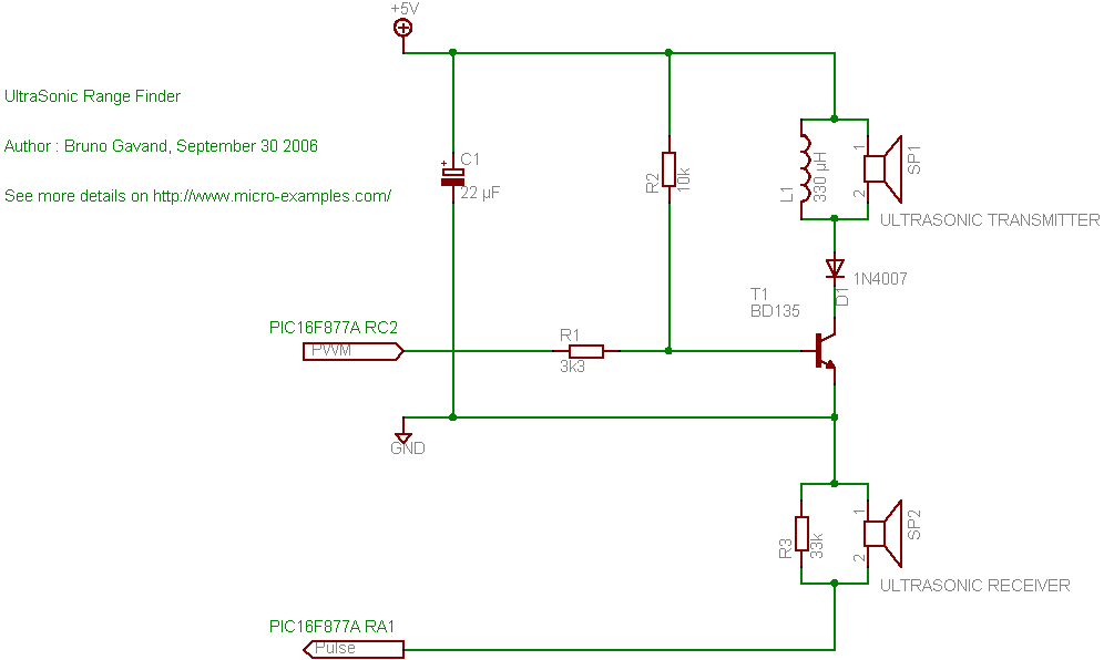
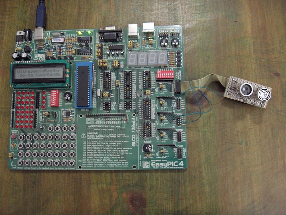
 * project      : Simple UltraSonic Range Finder
 * author       : Bruno Gavand
 * compiler     : mikroC V6.2
 * date         : september 30, 2006
 *
 * description  :
 *      This is a basic ultrasonic range finder, from 30 to 200 centimeters
 *
 * target device :
 *      PIC16F877A with 8 Mhz crystal
 *      or any PIC with at least one ADC and PWM channel
 *
 * configuration bits :
 *      HS clock
 *      no watchdog
 *      no power up timer
 *      no brown out
 *      LVP disabled
 *      data EE protect disabled
 *      ICD disabled
 *
 * see more details and schematic on http://www.micro-examples.com/
 */
 
/********************
 * MACRO DEFINITIONS
 ********************/
/*
 * ultra sonic pulse length in microseconds
 */
#define PULSELEN        300

/*
 * circular buffer size for samples averaging
 */
#define BUFSIZE 10

/*
 * LCD PORT
 * EasyPic2, EasyPic3 : PORTB
 * EaspyPic4 : PORTD
 */
#define LCDPORT PORTD
#define LCDTRIS TRISD

/*******************
 * GLOBAL VARIABLES
 *******************/
unsigned char   outOfRange ;            // out of range flag : set when no echo is detected

unsigned int    buf[BUFSIZE] ;          // samples buffer
unsigned char   idx = 0 ;               // index of current sample in buffer

/*****************************************
 * INTERRUPT SERVICE ROUTINE
 * This ISR handles TIMER1 overflow only
 *****************************************/
void    interrupt(void)
        {
        if(PIR1.TMR1IF)                                       // timer1 overflow ?
                {
                outOfRange = 1 ;                              // set out of range flag
                PIR1.TMR1IF = 0 ;                             // clear interrupt flag
                }
        }

/************
 * MAIN LOOP
 ************/
void    main()
        {
        ADCON1 = 0 ;            // enables ADC
       
        TRISA = 0xff ;          // PORTA as inputs
        PORTA = 0 ;

        TRISC = 0 ;             // PORTC as outputs
        PORTC = 0 ;

        // TIMER1 settings
        T1CON = 0b00001100 ;    // prescaler 1:1, osc. enabled, not sync, internal clk, stopped
       
#ifdef   LCDPORT
        // init LCD
        Lcd_Init(&LCDPORT) ;            // use EP2/3/4 settings
        Lcd_Cmd(Lcd_CLEAR) ;            // clear display
        Lcd_Cmd(Lcd_CURSOR_OFF) ;       // cursor off

        Lcd_Out(1, 1, "UltraSonicRanger") ;
        Lcd_Out(2, 5, "cm") ;
#endif

        // init PWM Channel : 40 Khz, 50% duty cycle
        PWM1_Init(40000) ;
        PWM1_Change_Duty(128) ;
       
        INTCON.GIE = 1 ;                // enable global interrupts
        INTCON.PEIE = 1 ;               // enable peripheral interrupts
        PIE1.TMR1IE = 0 ;               // disable timer 1 interrupt
        PIR1.TMR1IF = 0 ;               // clear timer 1 interrupt flag

        // forever
        for(;;)
                {
                unsigned char   i ;             // general purpose byte
                unsigned long   cm ;            // distance in centimeters
                unsigned char   str[4] ;        // string for range display

                // prepare timer
                T1CON.TMR1ON = 0 ;              // stop timer
                outOfRange = 0 ;                // reset out of range flag
                TMR1H = 0 ;                     // clear timer1
                TMR1L = 0 ;

                T1CON.TMR1ON = 1 ;              // start timer 1
                PIE1.TMR1IE = 1 ;               // enable timer 1 interrupts on overflow

                // send pulse
                PWM1_Start() ;                  // enable PWM output : transducer is pulsed at ultrasonic frequency
                Delay_us(PULSELEN) ;            // during PULSELEN microseconds
                PWM1_Stop() ;                   // stop PWM

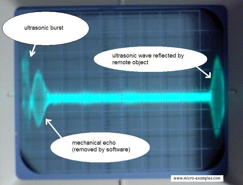
                Delay_us(PULSELEN * 2) ;        // do nothing for twice the pulse length duration to prevent false start

                while(Adc_Read(1) < 1)         // while no pulse detected (no signal on ADC channel 1)
                        {
                        if(outOfRange) break ;  // to late, out of range
                        }

                T1CON.TMR1ON = 0 ;              // stop timer 1
                PIE1.TMR1IE = 0 ;               // disable timer 1 interrupts on overflow

#ifdef LCDPORT
                if(outOfRange)                          // is overrange condtion detected ?
                        {
                        Lcd_Out(2, 8, "OverRange") ;    // display overrange message
                        }
                else if(TMR1H < ((PULSELEN * 6 * Clock_kHz()) / (1000 * 4 * 256)))      // is underrange condition detected ?
                        {
                        Lcd_Out(2, 8, "UnderRnge") ;    // display underrange message
                        }
                else                                    // good reading
                        {
                        buf[idx] = TMR1H ;              // build a 16 bit value from timer1
                        buf[idx] <<= 8 ;                // MSB
                        buf[idx] += TMR1L ;             // LSB

                        // circular buffer
                        idx++ ;                         // next location
                        if(idx == BUFSIZE)              // the end is reached ?
                                {
                                idx = 0 ;               // back to start
                                }

                        cm = 0 ;                        // prepare centimeter averaging
                        for(i = 0 ; i < BUFSIZE ; i++)  // for all samples in buffer
                                {
                                cm += buf[i] ;  // add to sum
                                }
                        cm /= BUFSIZE ;             // average samples

                        /*
                         * cm contains now the number of clock cycles
                         * from the start of the ultrasonic transmission
                         * to the first echo detection
                         * the duration in second is s = cm / (Clock_Khz() * 1000 / 4)
                         * if we admit that sound speed in the air is 340 m/s
                         * the distance in centimeters (forth and back) is d = s * 340 * 100 / 2
                         * or d = 340 * 100 / 2 * cm / Clock_khz() / 1000 * 4
                         * d = 34 * 2 / Clock_Khz()
                         */
                        cm *= 34 * 2 ;                  // now converts to centimeters
                        cm /= Clock_Khz() ;

                        ByteToStr(cm, str) ;            // convert to string
                        Lcd_Out(2, 1, str) ;            // print string
                        Lcd_Out(2, 8, "         ") ;    // clear error message
                        }
#endif

                Delay_ms(10) ;                          // 10 milliseconds delay before next sample
                }
        }

INSTRUCTIONS FOR USE

I tested it with an EasyPic4 development board :

ultrasonic range finder connected to Easypic4 board


Of course, this ranger is very basic and have a few drawbacks :

A little shock to the piezzo receiver cell could lead to a wrong measurement,

Since ultrasonic pulse is not coded, any other ultrasonic source will put the mess :

=> Unwanted underflow or overflow conditions may happen

This is the price of the very simple design of the ranger.


This is what you should see on your scope, if you probe to the ultrasonic receiver pins :

ultrasonic range finder scope screen capture

Horizontal : 1 ms/div
Vertical : 5 mV/div

The mechanical echo is removed by a software delay.
The reflected wave is around 40 mV peak to peak, it comes around 9.5 ms after the ultrasonic burst, if we say that sound velocity is 340 m/s it means that the object distance was around 0.0095 / 2 * 340 = 1.615 meters.
Actually, it was the ceiling, it was 172 cm above the circuit, the LCD wrote 170 cm.

I hope this basic project will make a good start for yours !

Please report bugs & comments in my forums


All trademarks and registered trademarks are the property of their respective owners