This example shows how to use a simple LED as light sensor, and to dim a 7-segments LED display with PWM automatically in the dark.
You will use :
the PIC analog input and its ADC
the PIC timer 0
a 4 digits 7 segments LED display
2 buttons
a simple LED diode
Did you ever use 7 segments LED display ? Of course yes.
Then you surely adjusted the brightness of the LED, so that it is clearly readable in the day light.
But what happens in the dark ? Your display is simply too much bright !
How to know if it is bright or dark, without adding an analog extra-circuit ?
How to control the brightness of the display, without adding an analog extra-circuit ?
1. A LED as light sensor ?
This is not big news :
A LED emits light when electricity passes from its anode to its cathode.
This may be an interesting news :
A LED emits electricity when light is applied to its silicon junction. How much electricity ? Not that much, but enough for our purpose, a few tenth of milliVolts at most. This could easily be read by the ADC of a PIC, by connecting its cathode to the ground and its anode to the input pin of the PIC.
But this is the real trick :
We will reverse the connections of the LED : its cathode will be connected to the input pin of the PIC, and its anode to the ground.
Why ? Shall we have to read a negative voltage value ? Will the PIC be destroyed by the negative voltage ? Will the LED fry, because it is reversed ?
Not at all !
Connecting the diode in reverse polarity to the PIC ADC input will have the effect :
In the dark : the silicon junction does not receive any light, and no voltage is present between its pin. In fact, the diode acts like an open circuit. Due to its internal structure (a charged capacitor), the PIC ADC will read in this case a 'phantom' voltage, and its value will be returned by the conversion.
In the light : the silicon junction of the LED is excited and a little voltage appears between its pins. As it is reversed to the 'phantom' voltage, the result voltage will be less than zero, and the PIC ADC will return a null value.
Of course, this reverse voltage is far away from being dangerous for your PIC, and no current drives through the LED to fry it : your circuit is safe !
2. Dimming the display
To dim the display, we have to reduce the amount of current that drives through the LED display.
To reduce the amount of current, the first idea is to reduce the current itself. Of course it is possible, but it would need some extra analog circuitry.
A better idea would be to reduce the period during which the current is supplied to the LEDs. The amount of current received by the display during a time unit will be less, and the display will dim. This can be done with software : 7 segments LED displays are usually time-multiplexed, some adjustments in the software will do the job, and no extra circuitry will be needed.
The software will do a kind of PWM (Pulse Width Modulation) : by adjusting its duty cycle, we control the brightness of the display.
With a 0% duty cycle, the display is switched off (the LEDs receive no current), with a 100% duty cycle, the display is turned on (the LEDs receive all the available current), otherwise the LEDs light proportionally to the duty cycle.
The software PWM for LED display is not that hard to code, because the PWM frequency involved is not very high, and not time-critical too.
3. Build the circuit
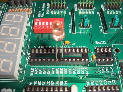
All that you have to do, is to insert the LED into the DIP28 socket of your Easypic. This socket has the advantage to have the RA5 pin and the Ground pin side by side, so that we don't need extra circuitry.
Plug the cathode of the diode into the RA5 hole, and the anode into the Ground hole. This should look like this :
This C source code will allow you to experiment your new light sensor. You can compile it with the MikroC compiler, it fits within the 2k demo limit (in fact less than 300 bytes of ROM), so that you don't need a licence key to build the binary file.
If you don't have already MikroC compiler for PIC on your PC, then download it now for free :
Open a new projet, select target device pic16f877a, copy/paste the source code, build the binary file and write it into your pic.
The source code of the software is fully documented, feel free to discuss it in my forums.
4. Run the program
Just turn off the light of the room and see the result on the display.
The LED is a very sensitive sensor : the display will dim only if there is no light at all.
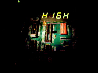
The message "HIGH" is printed on the display when the LED sensor receives the light of a lamp, and then the message "DIMM" is printed with a dimmed brightness when the light goes off.
(WMV, 1.2 Mo)
To adjust the brightness of the dimmed display, press the RD0 or RD1 keys : the PWM duty cycle will change and the brightness of the display too.
If you enable PORTC LEDs, the duty cycle is shown as a bar graph.
5. Try other LEDS
Try with all LEDs you have : depending on their diameters and colors, sensitivity may vary.
Enjoy and please report your own experiments in the forums !
All trademarks and registered trademarks are the property of their respective owners
 This example shows how to use a simple LED as light sensor, and to dim a 7-segments LED display with PWM automatically in the dark.