You will learn that any silicon diode, and widely any silicon junction have an almost-linear temperature coefficient of about 2.3 mV/°C when a forward voltage is supplied across the junction.
I suggest to use a diode : you can't find cheaper sensor, and you surely have one. Any 1N4148, 1N4004 will do the job.
2. Build the circuit
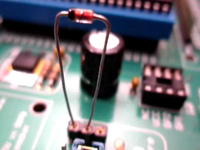
All that you have to do, is to insert the diode in the TS1 socket of your Easypic.
Plug the cathode of the diode into the upper hole of the socket, and the anode into the middle hole. The 10k pull-up resistor will bias the diode with a ~0.5mA current, almost what we need (1mA would be better).
This should look like this :
Your sensor is in place !
Then set up your EP3 board as follow :
put a pic16f877a in the dip40 socket
put a 8 Mhz crystal in the oscillator socket
set JP14 jumper to select RE2 pin
set SW2 switches 5 to 8 to ON, to enable 7segment LED display
This C source code will allow you to experiment your new temperature sensor. You can compile it with the MikroC compiler, it fits within the 2k demo limit (in fact less than 800 bytes of ROM), so that you don't need a licence key to build the binary file.
If you don't have already MikroC compiler for PIC on your PC, then download it now for free :
Open a new projet, select target device pic16f877a (or any 40 pins pic device), copy/paste the source code, build the binary file and write it into your pic.
The source code of the software is fully documented, feel free to discuss it in my forums.
4. Run the program
First, you will have to select either Fahrenheit or Celcius display for the temperature. Press the RD7 button to toggle between °F or °C.
Then you will have to calibrate your diode. The forward voltage of a silicon junction is around 0.6V at 25°C, but it may vary a lot from a diode to another.
You will have to know the temperature of your room : you will have to press RD0 to increase the temperature displayed, or RD1 to decrease it, until it is the same than your reference thermometer.
You will notice that temperature will jump by steps of around 2°C : that's normal ! Don't forget that the diode has a 2.3mV/°C temperature coefficient, whereas one bit of the pic ADV is 5000/1024 = 4.88mV ! Without extra-component, like an operational amplifier, we only have a 2°C accuracy. That's the price of the extreme simplicity of our circuit.
We suppose that all silicon junctions have the same temperature coefficient, and we don't need to calibrate or adjust it. If you think that it is not enough good for your project, then refer to the datasheet of your diode and apply the new coefficient in the program.
5. Try other silicon sensors
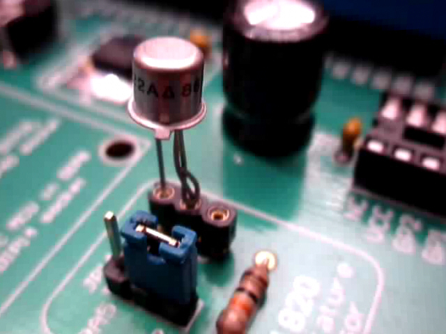
You can try with a NPN transistor : just tie its base and collector together to make it work in diode mode.
Here is a 2N2222 NPN transistor in diode mode as temperature sensor, you will have to re-calibrate the display with RD0 and RD1 buttons.
It works much more slowly than the diode, because of its metal case.
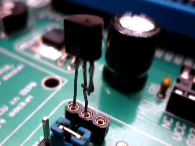
You can try with a MTS102 temperature sensor : it is nothing else but a transistor !