How to add a programming status LED to your EasyPIC3 development board
I did it to my EasyPIC2 board, now it's time to do it to my EasyPIC3 board !
Do you want to light a LED when programming your PIC is in progress ?
Follow this steps, it will take 10 minutes of your time, and after this you will not need to watch your screen anymore when you flash your program into your MCU : just wait for the LED to turn off.
What do you need ?
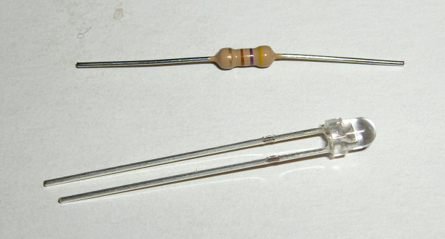
Here are the parts you need : a resistor and a LED.
I used a 3mm red LED but any will do the job.
The LED will be powered with +5V, select the correct resistor value for your LED (470 ohms for mine) to limit the current.
Where to place it ?
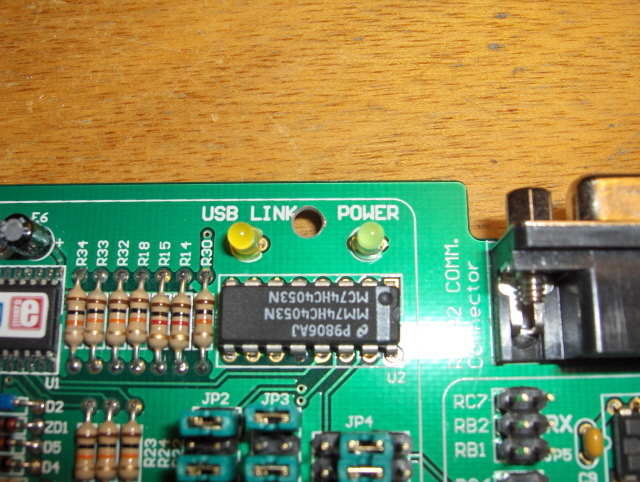
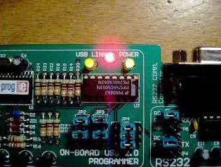
The perfect place would be between USB LINK LED and POWER LED, but there is a track in between, so that I had to shift it up a little bit.
After drilling a 3mm hole, it looked like this :
Component side
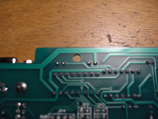
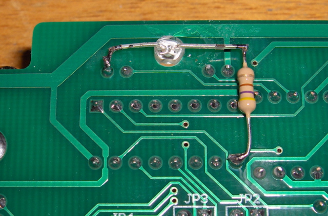
Solder side
How to connect it ?
The LED is powered directly by the USB PIC programmer's output that drives the 4053 analog switch, so that the LED will light when the user's PIC is connected to the programming circuit, instead of the development board circuit. Please do this very carefully because any damage to the programmer's circuitry would mean the end of your board, so be sure of what you do, and do it under your own responsibility.
1/ Insert the LED through the hole, with the cathode pin to the POWER LED side.
This should look like this :
2/ Glue to LED to the board
3/ Solder the LED cathode (left pin on the picture) to the left pin of the POWER LED : it is connected to the ground of the board
3/ Solder the LED anode (right pin on the picture) to the resistor
4/ Solder the other pin of the resistor to the pin 9 of the 4053 analog switch IC : it is the switch command line
5/ Verify that both LED and resistor are firmly in place, and ensure that there is no short circuit with other tracks
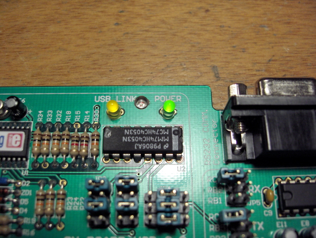
Test it now !
Plug the board : everything should be as usual.
Now launch PicFlash2 : the LED lights during programming. Great, it works ! I love it already !
 I did it to my