Single-digit Nixie, sequential hours, minutes and seconds display
DCF-77 atomic clock, with automatic or manual time set-up
high voltage power supply for Nixie with only 4 components
24 hours cycle programmable extinction time
no MikroC compiler licence needed !
This project will show you how to drive a nixie tube display with a
PIC16F84A simple microcontroller.
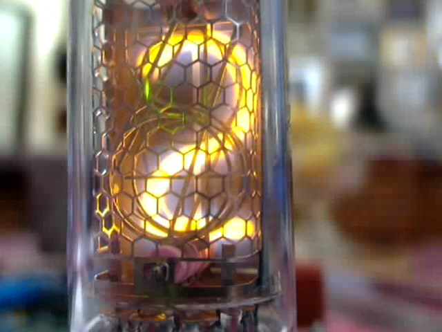
The nixie is a vertical-mount, front-reading IN-14 russian tube (thanks Alex
!), very convenient for prototyping because of its long solderable pins.
How to power the nixie ?
A 170 volt power supply must be applied between the anode
of the tube and one of its cathod, to light the corresponding number from 0 to
9. The lightened number needs around 1.5 mA to glow.
If the voltage is lower, the number is not completely lightened and may even
extinguish (under 140 V).
If the voltage is higher, digits will randomly light at the same time, and no
digit will be clearly readable.
It is possible to get the high voltage from the main power supply, but it is
highly dangerous because live parts may be exposed to dangerous voltage.
That's why is use a DC/DC converter, which gives the +170V needed by the
nixie from the +5V power supply of the circuit.
The PIC16F84A generates a software PWM, and drives the MOSFET's
gate. The MOSFET switches on an off the current into a 300 µH coil. The inducted
high voltage is collected by a fast recovery diode and then fed into a
capacitor.
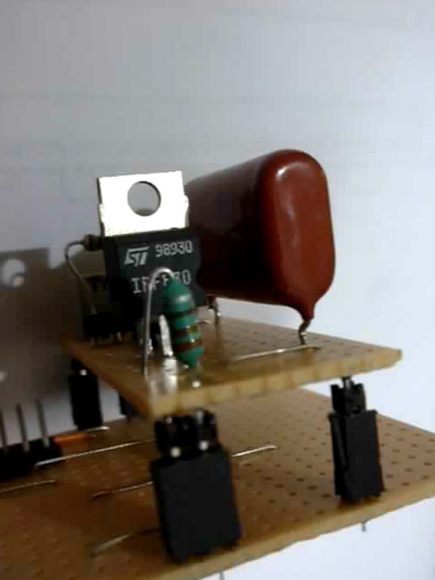
This is a close-up view, showing the IRF830 MOSFET, the 330 µH miniature
coil, and the big 2.2 µF 250V capacitor.
Note that the power supply is build as an individual board, I use it also in
other test boards for other projects.
A simple resistor divider feeds back a voltage reference into a PIC input :
if the voltage exceeds the 1 level of the PIC, the software turns PWM off, until
the voltage turns under the 1 level of the PIC : then the PWM output starts
again, and so on... this allows to keep a constant high voltage of around +170
V, depending on the variable resistor setting.
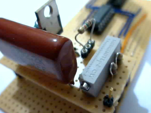
This is a close-up of the voltage reference
divider.
We can also see that the 15 K anode current limiting resistor is mounted on a
socket : during tests, a 47 K resistor was used.
Remember this : reducing the current will increase the life of your tube !
You have to find a good value for a good brightness and a long life.
Power supply adjustment : turn the variable potentiometer, so that you can
read around 175 V on a voltmeter connected to the test point (see
schematic).
Don't forget that there is a 2.2 µF
capacitor charged with +170 V in the circuit. This is enough to hurt you VERY
BADLY if you touch it.
How to drive the nixie ?
The anode is connected to the high voltage through a 15 K resistor, in order
to limit the current to approximately 1.5 mA. It is not possible to drive the
cathodes with the pic output, because of the high voltage engaged.
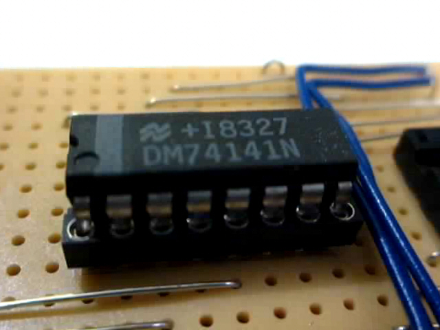
I use a 74141 IC, which has been designed for nixie tubes : it includes a BCD
to decimal decoder, and each output has a high-voltage transistor.
74141 close-up : it may turn hard to find it !
You can try to use also 7441 IC, but it will not blank the outputs with BCD
input greater than 9.
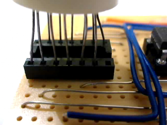
I didn't want to solder the nixie tube directly to my
prototype board, that's why I plugged it on a 14 pins dual-in-line IC
socket.
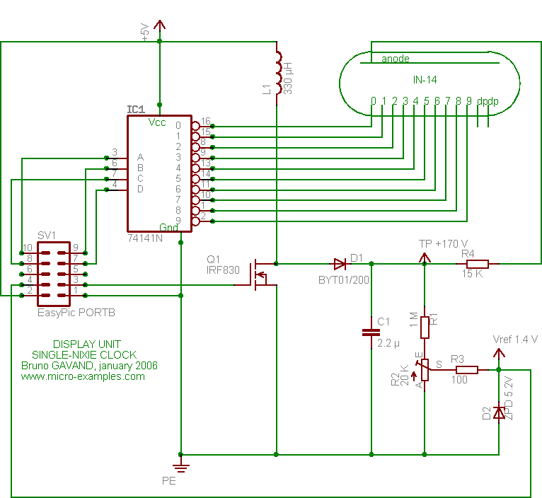
Circuit schematic
This is the schematic of my prototype board :
Click on the schematic to enlarge an get a full-sized picture
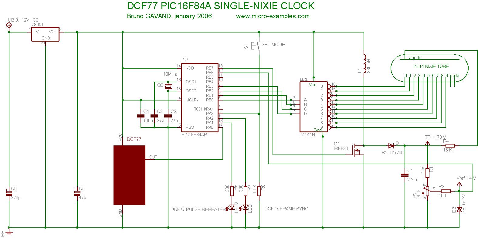
This is the schematic of the full circuit (click on the picture to enlarge)
:
As you can see, the power supply (+5V) comes from the EasyPic board.
The two decimal points (left & right) of the IN-14 tube are not used in
this project.
R3 and D2 protect the pic input in case of the voltage turns to high if the
regulation fails.
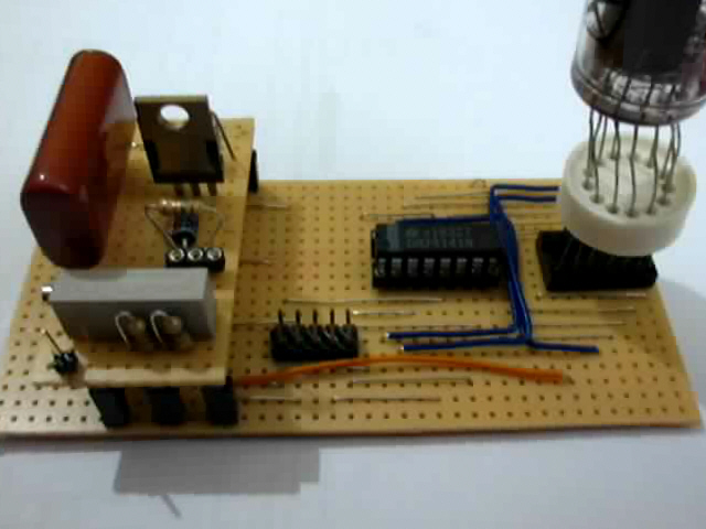
This is the prototype board, with from left to right :
- the high voltage power supply
- the connector (to connect the board to the Easypic PORTB)
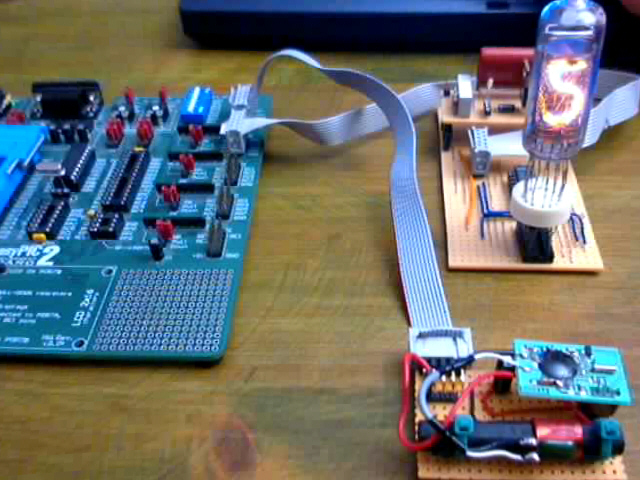
 Here is the nixie clock !